Revision 5
93
August 2021
Zero Purge (sec)
Y
Config – Timers/Alarms
Time interval during a zero calibration cycle
after switching to back purge and before
calculating the new zero baseline
Zero Hold (sec)
Y
Config – Timers/Alarms
Time interval during a zero calibration cycle
after the analyzer has switched back to
sampling mode and prior to the analyzer
concentration outputs configured for Hold
being updated again.
Integration Time (ms)
Y
Spectrum
Amount of time light is collected by
spectrometer before the intensity is read to
produce a spectrum
Fixed Temperature
(Enable)
Y
Config – Calculation
Enable and select a fixed temperature value
for temperature compensation of results
NOTE: Live cell temperature value will be
used for temperature compensation if
this is not enabled.
Fixed Pressure (Enable)
Y
Config – Calculation
Enable and select a fixed pressure value for
pressure compensation of results
Note: Live cell pressure value will be
used for pressure compensation if this is
not enabled.
Measure Analog Input 3
N
N/A
Enable the measurement of a concentration
sensor connected to Analog Input 3 on the
IO Board. If enabled, this measurement will
be displayed on the
Analysis 2
panel of the
local display.
Analog Input 3 is
Hydrogen
N
N/A
Enable the measurement of Hydrogen via a
sensor connected to Analog Input 3 on the
IO board. If this option and the previous
option are enabled, this measurement will be
displayed on the
Analysis 2
panel of the
local display.
Sample Rate
Y
Config – Calculation
Rate at which the displays and output data
are updated when the analyzer is in
sampling mode
Zero Sample Rate
Y
Config – Calculation
Rate at which the displays and output data
are updated when the analyzer is in back
purge mode.
When the page is first opened, it is opened in Read Only mode, which means that the values
for the displayed parameters can only be viewed, not edited. To edit the parameters, first
click on
Change to Update Mode (
at the top right of the screen. The
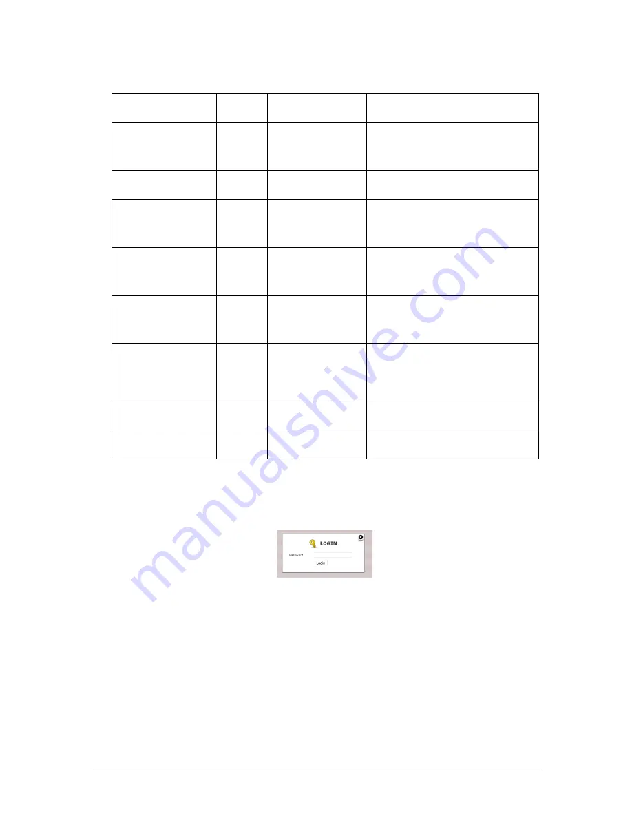
LOGIN
dialog box
shown in Figure 61 will then appear.
Figure 61: Login Dialog Box
Enter in the correct password, then click
Login.
To change a parameter:
1. Click on the parameter to be edited. The data entry field for that parameter will change
to a white background.
2. Edit the parameter by typing in a new value. Some parameters such as
Fixed
Temperature Enable
are non-numerical and can be edited by using the pull-down
selection menu.
3. Once editing of the selected field is complete, press Enter
on the keyboard.
4. Change any other parameters to be edited using the procedure in steps 1 to 3.
Summary of Contents for 943-TGS-CE
Page 137: ...Revision 5 137 August 2021 Figure 84 Oven Cabinet Details...
Page 138: ...Revision 5 138 August 2021 Figure 85 Control Cabinet Door Closed...
Page 139: ...Revision 5 139 August 2021 Figure 86 Control Cabinet Door Removed...
Page 140: ...Revision 5 140 August 2021 Figure 87 Power Steam Air Signals Connection Details...
Page 141: ...Revision 5 141 August 2021 Figure 88 AC Wiring Schematic...
Page 142: ...Revision 5 142 August 2021 Figure 89 DC Signals and Wiring Diagram...
Page 143: ...Revision 5 143 August 2021 Figure 90 Flow Diagram...
Page 144: ...Revision 5 144 August 2021 Figure 91 Control and Oven Cabinets Interconnect Wiring...


