1. INSTALLATION & WIRING
1-3
Flush mount
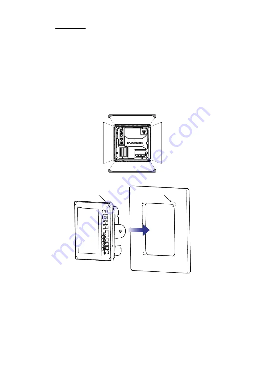
The flush mount kit (available for separate purchase) is required to mount the unit in
a console/bulkhead. Select a flat mounting location, and install the unit as shown be-
low.
Note 1:
It is recommended to set up a dedicated breaker when flush mounting the unit,
since it will be difficult to disconnect cables after the unit is installed.
Note 2:
Wiring and connection before setting the unit into the mounting location is rec-
ommended.
1. Using the supplied template, make a cutout and drill four pilot holes in the mount-
ing location.
2. Place the display unit on a flat, clean, soft area, then set the supplied flush mount-
ing sponge to the display unit.
3. Set the display unit to the cutout.
4. Open the four screw covers (on each corner of the unit face), then fasten the four
supplied screws to secure the unit in place.
5. Attach the screw cover back into place.
Pilot holes
Screw-hole covers
Summary of Contents for FR-10
Page 1: ...OPERATOR S MANUAL www furuno com MARINE RADAR Model FR 10 FR 12 ...
Page 16: ...EQUIPMENT LIST xiv This page is intentionally left blank ...
Page 36: ...1 INSTALLATION WIRING 1 20 This page is intentionally left blank ...
Page 122: ...6 RADIO OPERATION 6 4 This page is intentionally left blank ...
Page 136: ...8 MAINTENANCE TROUBLESHOOTING 8 8 This page is intentionally left blank ...
Page 163: ...D 1 1 F eb 2 022 H M AKI ...
Page 164: ...D 2 1 Feb 2022 H MAKI ...
Page 165: ...D 3 1 Feb 2022 H MAKI ...
Page 166: ...D 4 1 Feb 2022 H MAKI ...


