


9-28
9.2.2
E Codes (Extension Terminal Functions)
E01 to E03
Terminal Command Assignment to [X1] to [X3]
Refer to E98 and E99.
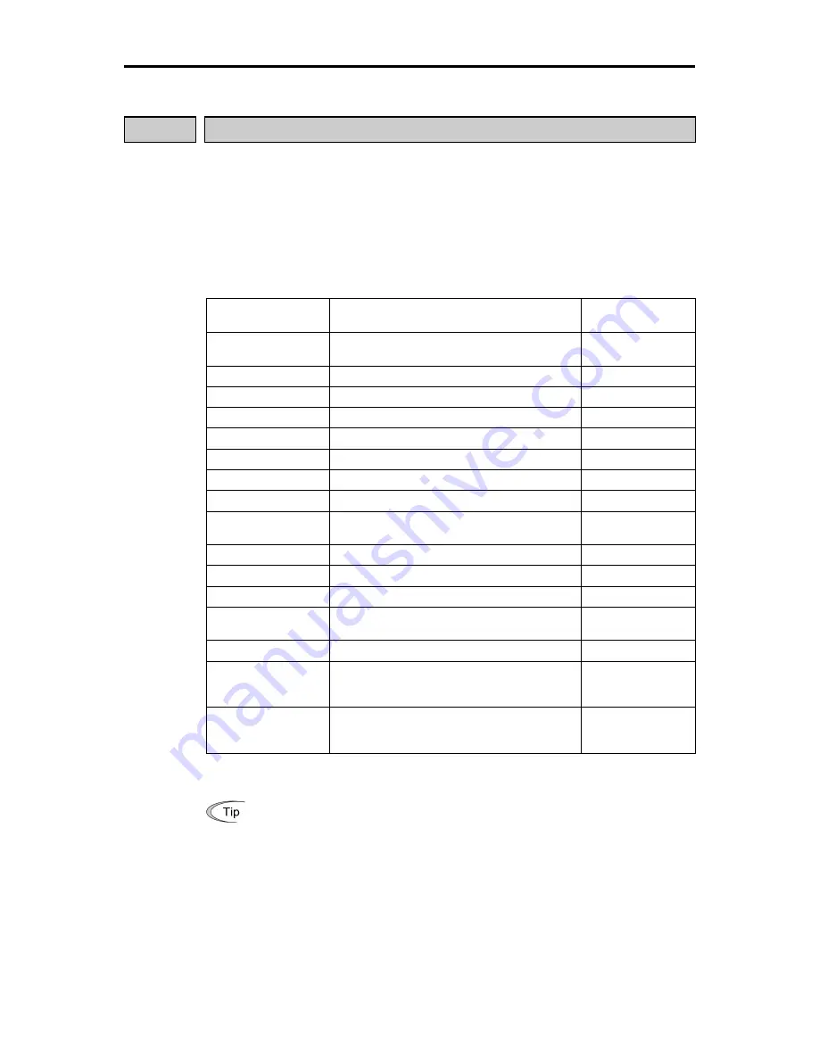
E01 to E03, E98 and E99 may assign commands (listed below) to terminals [X1] to [X3],
[FWD], and [REV] which are general-purpose programmable input terminals.
These function codes may also switch the logic system between normal and negative to
define how the inverter logic interprets either ON or OFF status of each terminal. The
default setting is normal logic, that is "Active ON."
To assign negative logic input to any input terminal, set the function code to the value of
1000s shown in ( ) in the table below. To keep explanations as simple as possible, the
examples shown below are all written for the normal logic system.
Set E01 to E03, E98
and E99 to:
To assign the following commands to
terminals:
Command symbols
(Input signals)
0,1,2
(1000,1001,1002)
Select multi-step frequency (1 to 7 steps)
(SS1), (SS2) and
(SS4)
4 (1004)
Select acceleration/deceleration (2 steps)
(RT1)
6 (1006)
Select self-hold, disabled 3-wire operations
(HLD)
7 (1007)
Coarse to a stop
(BX)
8 (1008)
Reset alarm (failure)
(RST)
9 (1009)
Alarm from external equipment
(THR)
10 (1010)
Ready for jogging
(JOG)
11 (1011)
Select frequency command 2 or 1
(Hz2/Hz1)
19 (1019)
Enable editing of function code data from the
keypad
(WE-KP)
20 (1020)
Disable PID control
(Hz/PID)
21 (1021)
Switch normal/inverted driving
(IVS)
24 (1024)
Enable link operation
(LE)
33 (1033)
Reset PID integral and differential
components
(PID-RST)
34 (1034)
Hold PID integral component
(PID-HLD)
98*
Run forward. Short-circuiting terminals
[FWD] and [CM] runs the motor forward.
Opening them decelerates the motor to stop
(FWD)
99*
Run reverse. Short-circuiting terminals [REV]
and [CM] runs the motor reverse. Opening
them decelerates the motor to stop
(REV)
* No negative logic input is allowed for data 98 and 99. Note that negative logic input can never be used
for the motor drive commands (FWD) and (REV).
(Example using negative logic system)
Assigning multi-step frequency 2 (SS2) to terminal [X1]
If function code E01 is set to 1, logic is normal ("Active ON"). Short-circuiting
terminals [X1] and [CM] makes (SS2) active.
If E01 is set to 1001, logic is negative ("Active OFF"). Opening the circuit
between [X1] and [CM] makes (SS2) active.
Summary of Contents for frenic mini series
Page 1: ...USER S MANUAL Fuji Electric Co Ltd MEH446...
Page 2: ...Compact Inverter User s Manual...
Page 62: ...4 4 4 3 Drive Command Generator Figure 4 2 Drive Command Generator...
Page 66: ...4 8 Figure 4 3 d Terminal Command Decoder ORing with Link Commands Ignoring Link Commands...
Page 68: ...4 10 4 5 Digital Output Selector Figure 4 4 Digital Output Signal Selector...
Page 70: ...4 12 4 6 Analog Output FMA Selector Figure 4 5 Analog Output FMA Selector...
Page 74: ...4 16 4 8 PID Frequency Command Generator Figure 4 7 PID Frequency Command Generator...
Page 81: ...Part 3 Peripheral Equipment and Options Chapter 6 SELECTING PERIPHERAL EQUIPMENT...
Page 124: ...Part 5 Specifications Chapter 8 SPECIFICATIONS Chapter 9 FUNCTION CODES...
Page 134: ...8 3 Common Specifications 8 9 Chap 8 SPECIFICATIONS 8 3 Common Specifications...
Page 135: ...8 10...
Page 257: ...App H Replacement Information A 33 App FVR C11S vs FRENIC Mini...
Page 261: ...Glossary This glossary explains the technical terms that are frequently used in this manual...


