58
PB
INSTALLATION
Installation of the Outdoor Unit
Connect Outdoor Electric Wire
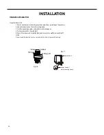
1. Put power connection wire and power wire through the wire‑‑passing hole.
2. Remove the wire clip; connect the power connection wire and power wire to the wiring terminal; fix them with screws.(As
show in Fig.23)
3. Fix the power connection wire and power wire with wire clip.
4. Install the cable cross plate sub‑assy.
Notes
1. After tightening the screw, pull the power cord slightly to check if it is firm.
2. Never cut the power connection wire to prolong or shorten the distance.
3. The connecting wire and connection pipe cannnot touch each other.
4. Top cover of outdoor unit and electric box assembly should be fixed by the screw. Otherwise, it can cause a fire, or short
circuit caused by water or dust.
Fig.23
cord clamp
cable cross
plate sub-assy
power connect wire
power wire
N(1)
N
N
L
L
3
2
Indoor unit connection
wire pipe
wire-passing
hole
Fixed nut
Finish
Summary of Contents for FSHW091
Page 8: ...8 INTRODUCTION FSHSW09A1A FSHSW12A1A Figure 102 Indoor Units FSHSW18A3A FSHSW24A3A FSHSW36A3A ...
Page 47: ...47 INSTALLATION ...
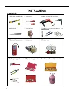
Page 48: ...48 INSTALLATION Installation Tools ...
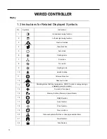
Page 72: ...72 WIRED CONTROLLER Display ...
Page 122: ...122 TROUBLESHOOTING Malfunction of IDUFanMotorU8 Service Manual No Start End ...
Page 146: ...146 WIRING DIAGRAMS Figure 8054 9 12KOutdoorUnitWiringDiagrams 60000706067401 3 2 N 1 C3 C4 ...
Page 158: ...158 FIgure 906 PARTS CATALOG 9KOutdoorUnit 28 27 29 31 30 32 ...
Page 160: ...160 PARTS CATALOG 12k OutdoorUnit 28 27 29 31 30 32 FIgure 907 ...

