30
PB
OPERATION
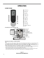
Remote Control Description
6.
▲/
▲
button
12.
TIMER ON / TIMER OFF button
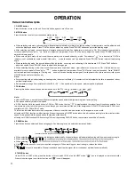
● Press "▲" or " ▲ " button once increase or decrease set temperature 1
°F
. Holding "▲" or " ▲ " button, 2s late
r
, set temperature on remote
(T
emperature can't be adjusted under auto mode)
● When setting
TIMER ON,
▲
TIMER OFF or CLOCK, press "▲" or " " button to adjust time. (Refer to CLOCK,
TIMER ON,
TIMER OFF
buttons)
10.
LIGHT button
Press
thi
s
button
to
turn
off
di
s
pla
y
ligh
t
on
indoor
unit.
"
display light. "
" icon is displayed.
11.
CLOCK button
● This function is only available for some models.
"
icon
on
remote
controller
di
s
appear
s. Press
thi
s
button
again
to
turn
on
9.
WIFI button
Press "
W
iF
i
" but
ton
t
o
turn
on
or
turn
off
W
iFi
func
t
ion.
W
hen
WiFi
function
i
s t
urned
on,
the "
W
iF
i
"
icon
will
be
displa
y
ed
on
remot
e
controller;
Under
status
of
remote
controller
off,
press
"
MODE
"
and
"
W
iFi
"
buttons
simultaneously
for
1s,WiFi
modulewill
restore
to
factory
default setting.
● Clock time adopts 24-hour mode.
● The interval between two operation can't exceeds 5s. Otherwise, remote controller will quit setting status. Operation for
TIMER ON/TIMER
OFF is the same.
Press
this
button
to
set
clock
time.
" "
icon
on
remote
controller
will
blink
. Press "
▲
"
or
"
▲
"
button
within
5
s
to
set
clock
time.
E
ac
h
pressing
of
"▲"
or
"
▲
"
button,
clock
time
will
increase
or
decrease
1
minute.
If
hold
"▲"
or
"
▲
"
button,
2s
late
r
,
time
will
change
quickl
y.
" icon stops blinking.
Note:
● TIMER ON button
"TIMER ON" button can set the time for timer on.
After pressing this button, " " icon disappears and the word "ON" on remot
e
controller
blinks. Press "▲" or " ▲ "button to adjust
TIMER ON setting.
After each pressing "▲" or " ▲ " button,
TIMER ON setting will increase or
decrease 1min. Hold "▲" or " ▲ " button, 2s late
r
, the time will change quickly until reaching your required time. Press "TIMER ON" to
" icon resumes displaying. Cancel
TIMER ON: Under the condition that
TIMER ON is
started up, press "TIMER ON" button to cancel it.
● TIMER OFF button
"TIMER OFF" button can set the time for timer off.
After pressing this button," " icon disappears and the word "OFF" on remo
te
controller blinks. Press "▲" or " ▲ " button to adjust
TIMER OFF setting.
After each pressing "▲" or " ▲ " button,
TIMER OFF setting will increase or decrease 1min. Hold "▲" or " ▲ " button, 2s late
r
, the time will change quickly until reaching your
required time. Press "TIMER OFF" word "OFF" will stop blinking. "
" icon resumes displaying. Cancel
TIMER OFF
. Under the condition
that
TIMER OFF is started up, press "TIMER OFF" button to cancel it.
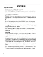
" or no display with remote controlle
r
, temperature indicator on indoor uni
t
displays set temperature.
" with remote controlle
r
, temperature indicator on indoor unit displays indoor ambient temperature.
" with remote controlle
r
, temperature indicator on indoor unit displays outdoor ambient temperature.
● When selecting "
● When selecting "
● When selecting "
Note:
"signal, while it displays indoor set
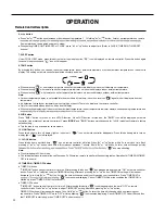
7.
SLEEP button
Under
COOL,
HEAT
mode,
press
this
button
to
start
up
sleep
function.
" "
icon
is
displayed
on
remote
controlle
r. Press
this
button
again
to cancel sleep function and " " icon will disappea
r.
8.
TEMP button
By
pressing
this
button,
you
can
see
indoor
set
temperature,
indoor
ambient
temperature
or
outdoor
ambient
temperature
on
indoor
units
displa
y.
The setting on remote controlleris selected circularly as below:
● Outdoor temperature display is not available for some models.
At that time, indoor unit receives "
temperature.
● Only for the models whose indoor unit has dual-8 displa
y.
● It's defaulted to display set temperature when turning on the unit.There is no display in the remote controlle
r.
● When selecting displaying of indoor or outdoor ambient temperature, indoor temperature indicator displays corresponding temperature and
no display
Summary of Contents for FSHW091
Page 8: ...8 INTRODUCTION FSHSW09A1A FSHSW12A1A Figure 102 Indoor Units FSHSW18A3A FSHSW24A3A FSHSW36A3A ...
Page 47: ...47 INSTALLATION ...
Page 48: ...48 INSTALLATION Installation Tools ...
Page 72: ...72 WIRED CONTROLLER Display ...
Page 122: ...122 TROUBLESHOOTING Malfunction of IDUFanMotorU8 Service Manual No Start End ...
Page 146: ...146 WIRING DIAGRAMS Figure 8054 9 12KOutdoorUnitWiringDiagrams 60000706067401 3 2 N 1 C3 C4 ...
Page 158: ...158 FIgure 906 PARTS CATALOG 9KOutdoorUnit 28 27 29 31 30 32 ...
Page 160: ...160 PARTS CATALOG 12k OutdoorUnit 28 27 29 31 30 32 FIgure 907 ...

