65
PB
REMOVAL
Indoor Unit
a
b
c
Procedure
Steps
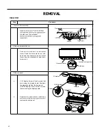
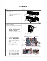
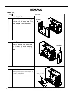
Loosen the connection clasps between
shield cover of electric box sub-assy and
electric box, and then remove the shield
cover of electric box sub-assy.
①
Take off the water retaining sheet.
Remove the cold plasma generator by
screwing off the locking screw on the
generator.
②
Take off the indoor tube temperature
sensor.
③
Screw off 1 grounding screw.
④
Remove the wiring terminals of motor and
stepping motor.
⑤
Remove the electric box assy.
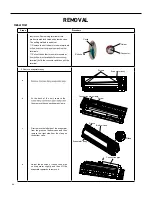
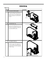
8. Remove electric box assy
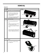
Electric box
Twist off the screws that are locking
each lead wire and rotate the electric
box assy.
Twist off the screws that are locking the
wire clip. Loosen the power cord and
remove it's wiring terminal. Lift up the
main board and take it off.
Electric box assy
Clasps
Shield cover of electric
box sub-assy
Cold plasma
generator
Water retaining
sheet
Grounding screw
Screw
Power cord
Wire clip
Screws
Main board
Screw
Indoor tube
temperature
sensor
Wiring
terminal
of motor
Wiring
terminal
of stepping
motor
Screw
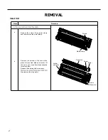
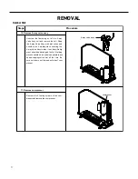
Vertical
louver
Vertical
louver
Clasps
Bottom
case
7. Remove vertical louver
Loosen the connection clasps between
vertical louver and bottom case to remove
vertical louver.
Summary of Contents for FSHW091
Page 8: ...8 INTRODUCTION FSHSW09A1A FSHSW12A1A Figure 102 Indoor Units FSHSW18A3A FSHSW24A3A FSHSW36A3A ...
Page 47: ...47 INSTALLATION ...
Page 48: ...48 INSTALLATION Installation Tools ...
Page 72: ...72 WIRED CONTROLLER Display ...
Page 122: ...122 TROUBLESHOOTING Malfunction of IDUFanMotorU8 Service Manual No Start End ...
Page 146: ...146 WIRING DIAGRAMS Figure 8054 9 12KOutdoorUnitWiringDiagrams 60000706067401 3 2 N 1 C3 C4 ...
Page 158: ...158 FIgure 906 PARTS CATALOG 9KOutdoorUnit 28 27 29 31 30 32 ...
Page 160: ...160 PARTS CATALOG 12k OutdoorUnit 28 27 29 31 30 32 FIgure 907 ...

