109
PB
COMPONENTS TESTING
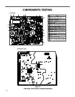
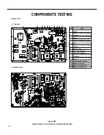
Figure 706
36k Outdoor Unit Printed Circuit Board Identification
●
Top view
●
Bottom view
No.
Name
No.
Name
No.
Name
1 High-frequency transformer T1
6 High pressure protection terminal HPP1
11 Terminal of neutral wire
2 Overload protection terminal of
compressor OVC-COMP
7 Terminal of 4-way valve
12 Protective tube FU101
3 Terminal of temp sensor CN2
8 Electric heater band of chassis HEAT2-L
13 Terminal of ground wire
4 High pressure protection terminal
HPP
9 Electric heater band of compressor
HEAT1-L
14 Choke L 101 and L102
5 Electronic expansion valve terminal
EV
10 Terminal of live wire
15 Terminal of outdoor fan
OFAN-DC
1
2
3
4
5
6
7
8
9
10
11
12
13
14
15
Summary of Contents for FSHW091
Page 8: ...8 INTRODUCTION FSHSW09A1A FSHSW12A1A Figure 102 Indoor Units FSHSW18A3A FSHSW24A3A FSHSW36A3A ...
Page 47: ...47 INSTALLATION ...
Page 48: ...48 INSTALLATION Installation Tools ...
Page 72: ...72 WIRED CONTROLLER Display ...
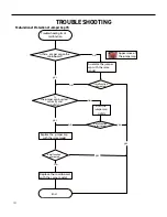
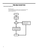
Page 122: ...122 TROUBLESHOOTING Malfunction of IDUFanMotorU8 Service Manual No Start End ...
Page 146: ...146 WIRING DIAGRAMS Figure 8054 9 12KOutdoorUnitWiringDiagrams 60000706067401 3 2 N 1 C3 C4 ...
Page 158: ...158 FIgure 906 PARTS CATALOG 9KOutdoorUnit 28 27 29 31 30 32 ...
Page 160: ...160 PARTS CATALOG 12k OutdoorUnit 28 27 29 31 30 32 FIgure 907 ...

