


MPC5553/MPC5554 Microcontroller Reference Manual, Rev. 5
Freescale Semiconductor
17-31
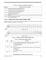
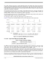
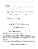
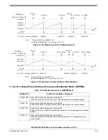
to indicate the start and end points of a complete period have been captured. This sequence of events is
repeated for each subsequent capture. Registers EMIOS_CADR
n
and EMIOS_CBDR
n
return the values
in register A2 and B1, respectively.
In order to guarantee coherent access, reading EMIOS_CADR
n
disables transfers between B2 and B1 until
reading EMIOS_CBDR
n
register, then any pending transfer is re-enabled.
The input pulse period is calculated by subtracting the value in B1 from A2.
shows how the unified channel can be used for input period measurement.
Figure 17-19. Input Period Measurement Example
17.4.4.4.6
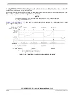
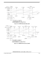
Double Action Output Compare Mode (DAOC)
In the DAOC mode the leading and trailing edges of the variable pulse width output are generated by
matches occurring on comparators A and B, respectively.
When the DAOC mode is first selected (coming from GPIO mode) both comparators are disabled.
Comparators A and B are enabled by updating registers A1 and B1 respectively and remain enabled until
a match occurs on that comparator, when it is disabled again. In order to update registers A1 and B1, a
write to A2 and B2 must occur and the EMIOS_CCR
n
[ODIS] bit must be cleared.
The output flip-flop is set to the value of EMIOS_CCR
n
[EDPOL] when a match occurs on comparator A
and to the complement of EDPOL when a match occurs on comparator B.
MODE[6] controls if the EMIOS_CSR
n
[FLAG] is set on both matches or just on the second match (see
If subsequent enabled output compares occur on registers A1 and B1, pulses will continue to be generated,
regardless of the state of the FLAG bit.
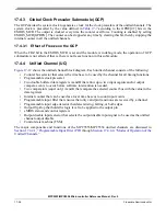
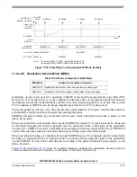
Table 17-19. Mode of Operation: DAOC Mode
MODE[0:6]
Unified Channel Mode of Operation
0b0000110
Double action output compare (with FLAG set on the second match)
0b0000111
Double action output compare (with FLAG set on both match)
0x000500
0x001000
0x001100
0x001250
0x001525
0x0016A0
Selected
Counter Bus
FLAG
Set Event
A
A
A
Captured A2
Value
2
0xxxxxxx
0x001000
0x0016A0
Notes:
1
After input filter.
2
Reading EMIOS_CADR
n
returns the value of
A2, writing EMIOS_CADR
n
writes to A2.
Input Signal
1
EDPOL = 1
B1 Value
3
0x001250
0xxxxxxx
0xxxxxxx
0x001250
0x001000
0xxxxxxx
0x001000
0x0016A0
0x001250
Captured B2
Value
3
Reading EMIOS_CBDR
n
returns the value of B1, writing EMIOS_CBDR
n
writes to
B1.
Summary of Contents for MPC5553
Page 5: ...MPC5553 MPC5554 Microcontroller Reference Manual Rev 5 2 Freescale Semiconductor...
Page 21: ...MPC5553 MPC5554 Microcontroller Reference Manual Rev 5 xvi Freescale Semiconductor...
Page 47: ...MPC5553 MPC5554 Microcontroller Reference Manual Rev 5 1 26 Freescale Semiconductor...
Page 163: ...MPC5553 MPC5554 Microcontroller Reference Manual Rev 5 4 20 Freescale Semiconductor...
Page 179: ...MPC5553 MPC5554 Microcontroller Reference Manual Rev 5 5 16 Freescale Semiconductor...
Page 561: ...MPC5553 MPC5554 Microcontroller Reference Manual Rev 5 13 38 Freescale Semiconductor...
Page 615: ...MPC5553 MPC5554 Microcontroller Reference Manual Rev 5 14 54 Freescale Semiconductor...
Page 707: ...MPC5553 MPC5554 Microcontroller Reference Manual Rev 5 17 68 Freescale Semiconductor...
Page 755: ...MPC5553 MPC5554 Microcontroller Reference Manual Rev 5 18 48 Freescale Semiconductor...
Page 873: ...MPC5553 MPC5554 Microcontroller Reference Manual Rev 5 19 118 Freescale Semiconductor...
Page 984: ...MPC5553 MPC5554 Microcontroller Reference Manual Rev 5 Freescale Semiconductor 21 41...
Page 985: ...MPC5553 MPC5554 Microcontroller Reference Manual Rev 5 21 42 Freescale Semiconductor...
Page 1019: ...MPC5553 MPC5554 Microcontroller Reference Manual Rev 5 22 34 Freescale Semiconductor...
Page 1129: ...MPC5553 MPC5554 Microcontroller Reference Manual Rev 5 25 90 Freescale Semiconductor...


