


MPC5553/MPC5554 Microcontroller Reference Manual, Rev. 5
Freescale Semiconductor
16-9
is set to 2.5
2
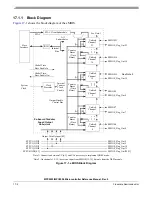
17
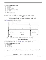
system clock periods. Then the BAM program reads the reset vector (
) from
the address 0x2000_0004 and branches to that reset vector address, starting user program execution.
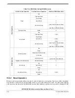
16.3.2.3
Serial Boot Mode Operation
In this mode of operation, the CAN_A and the eSCI_A GPIO signals are reconfigured, unused message
buffers in CAN_A are used as scratch pad RAM, the MMU is setup; the watchdog is enabled. No
exceptions are used.
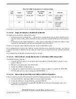
16.3.2.3.1
Serial Boot Mode MMU and EBI Configuration
The BAM program sets up the MPC5553/MPC5554 MMU for all peripheral and memory regions in one
of two different modes and sets up the EBI in one of three different modes; depending on how serial boot
mode was entered.
If serial boot mode is entered directly by choosing the mode with the BOOTCFG signals, or was entered
indirectly from internal boot mode because no valid RCHW was found, then the MMU is configured the
same way as for internal boot mode. See
for more information. The EBI is disabled and all bus
pins function as GPIO.
If serial boot mode is entered indirectly from either external boot/single master or external
boot/multimaster/external arbitration because no valid RCHW was found, then the MMU and EBI are
configured the same way as for one of the external boot modes with a 16-bit data bus. See
for
more information.
16.3.2.3.2
CAN and eSCI Configuration
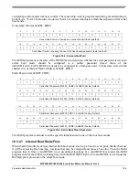
In serial boot mode, the BAM program configures CAN_A and eSCI_A to receive messages. The
CNRX_A signal and the RXD_A signals are configured as inputs to the CAN and eSCI modules. The
CNTX_A signal is configured as an output from the CAN module. The TXD_A signal of the eSCI_A
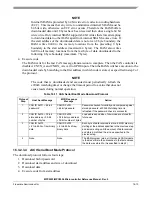
remains configured as GPIO input. The BAM program writes the e200z6 core timebase registers (TB) to
0x0000_0000_0000_0000 and enables the e200z6 core watchdog timer to use the system clock and to
cause a reset after a time-out period of 3 x 2
27
system clock cycles. (See
for examples of time
out periods.)
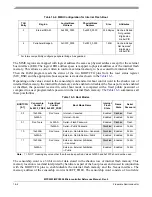
In serial boot mode the CAN controller is configured to operate at a baud (bit) rate equal to the system
clock frequency divided by 60 with one message buffer (MB) using the standard 11-bit identifier format
detailed in the CAN 2.0A specification.
If the PLL is enabled out of reset, the default system clock is 1.5 times the crystal frequency. (See
Chapter 11, “Frequency Modulated Phase Locked Loop (FMPLL) and System Clocks
,” for more
information.) So with the PLL enabled, the baud rate is equal to the crystal frequency divided by 40.
shows CAN operation at reset.
shows examples of baud rates.
Table 16-7. BAM CAN Frequency at Reset (FMPLL Enabled out of Reset)
FMPLL Clock Mode
System Clock
Frequency after Reset
Serial Boot Mode Frequency
1
(CAN Baud Rate)
1
Serial boot mode frequency is set in software as the system clock frequency divided by 60.
Crystal Reference Mode or
External Reference Mode
1.5 x Crystal Reference
Frequency
2
2
Crystal reference frequency can be 8 – 20MHz.
Crystal Reference Frequency / 40
Dual Controller Mode
2 x EXTCLK
EXTCLK / 30
Summary of Contents for MPC5553
Page 5: ...MPC5553 MPC5554 Microcontroller Reference Manual Rev 5 2 Freescale Semiconductor...
Page 21: ...MPC5553 MPC5554 Microcontroller Reference Manual Rev 5 xvi Freescale Semiconductor...
Page 47: ...MPC5553 MPC5554 Microcontroller Reference Manual Rev 5 1 26 Freescale Semiconductor...
Page 163: ...MPC5553 MPC5554 Microcontroller Reference Manual Rev 5 4 20 Freescale Semiconductor...
Page 179: ...MPC5553 MPC5554 Microcontroller Reference Manual Rev 5 5 16 Freescale Semiconductor...
Page 561: ...MPC5553 MPC5554 Microcontroller Reference Manual Rev 5 13 38 Freescale Semiconductor...
Page 615: ...MPC5553 MPC5554 Microcontroller Reference Manual Rev 5 14 54 Freescale Semiconductor...
Page 707: ...MPC5553 MPC5554 Microcontroller Reference Manual Rev 5 17 68 Freescale Semiconductor...
Page 755: ...MPC5553 MPC5554 Microcontroller Reference Manual Rev 5 18 48 Freescale Semiconductor...
Page 873: ...MPC5553 MPC5554 Microcontroller Reference Manual Rev 5 19 118 Freescale Semiconductor...
Page 984: ...MPC5553 MPC5554 Microcontroller Reference Manual Rev 5 Freescale Semiconductor 21 41...
Page 985: ...MPC5553 MPC5554 Microcontroller Reference Manual Rev 5 21 42 Freescale Semiconductor...
Page 1019: ...MPC5553 MPC5554 Microcontroller Reference Manual Rev 5 22 34 Freescale Semiconductor...
Page 1129: ...MPC5553 MPC5554 Microcontroller Reference Manual Rev 5 25 90 Freescale Semiconductor...


