


MPC5553/MPC5554 Microcontroller Reference Manual, Rev. 5
Freescale Semiconductor
13-3
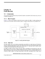
13.1.3
Features
The following list summarizes the key features of the FBIU:
•
The FBIU system bus interface supports a 64-bit data bus. Byte, halfword, word, and doubleword
reads are supported. Only aligned word and doubleword writes are supported.
•
The FBIU provides configurable read buffering and line prefetch support. Two line read buffers
(256 bits wide) and a prefetch controller are used to support single-cycle read responses for hits in
the buffers.
•
The FBIU provides hardware and software configurable read and write access protections on a
per-master basis.
•
The FBIU interface to the flash array controller is pipelined with a depth of 1.
•
The FBIU allows configurable access timing.
•
The FBIU provides multiple-mapping support and mapping-based block access timing (0–31
additional cycles) allowing for emulation of other memory types.
The flash memory array has the following features:
•
Software programmable block program/erase restriction control for low, mid, and high address
spaces
•
Erase of selected blocks
•
ECC with single-bit correction, double-bit detection
•
Page program of one to eight consecutive 32-bit words within a page (recommended minimum is
two words due to ECC)
•
Embedded hardware program and erase algorithm
•
Read while write with multiple partitions
•
Stop mode for low-power stand-by
•
Erase suspend, program suspend, and erase-suspended program
•
Automotive flash that meets automotive endurance and reliability requirements. Shadow
information is stored in a non-volatile shadow block
•
Independent program/erase of the shadow block
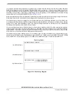
13.1.4
Modes of Operation
13.1.4.1
User Mode
User mode is the default operating mode of the flash memory block. In this mode, it is possible to read,
write, program, and erase the flash. Refer to
Section 13.4.2, “Flash Memory Array: User Mode
.”
13.1.4.2
Stop Mode
In stop mode (FLASH_MCR[STOP] = 1), all DC current sources in the flash are disabled. Refer to
Summary of Contents for MPC5553
Page 5: ...MPC5553 MPC5554 Microcontroller Reference Manual Rev 5 2 Freescale Semiconductor...
Page 21: ...MPC5553 MPC5554 Microcontroller Reference Manual Rev 5 xvi Freescale Semiconductor...
Page 47: ...MPC5553 MPC5554 Microcontroller Reference Manual Rev 5 1 26 Freescale Semiconductor...
Page 163: ...MPC5553 MPC5554 Microcontroller Reference Manual Rev 5 4 20 Freescale Semiconductor...
Page 179: ...MPC5553 MPC5554 Microcontroller Reference Manual Rev 5 5 16 Freescale Semiconductor...
Page 561: ...MPC5553 MPC5554 Microcontroller Reference Manual Rev 5 13 38 Freescale Semiconductor...
Page 615: ...MPC5553 MPC5554 Microcontroller Reference Manual Rev 5 14 54 Freescale Semiconductor...
Page 707: ...MPC5553 MPC5554 Microcontroller Reference Manual Rev 5 17 68 Freescale Semiconductor...
Page 755: ...MPC5553 MPC5554 Microcontroller Reference Manual Rev 5 18 48 Freescale Semiconductor...
Page 873: ...MPC5553 MPC5554 Microcontroller Reference Manual Rev 5 19 118 Freescale Semiconductor...
Page 984: ...MPC5553 MPC5554 Microcontroller Reference Manual Rev 5 Freescale Semiconductor 21 41...
Page 985: ...MPC5553 MPC5554 Microcontroller Reference Manual Rev 5 21 42 Freescale Semiconductor...
Page 1019: ...MPC5553 MPC5554 Microcontroller Reference Manual Rev 5 22 34 Freescale Semiconductor...
Page 1129: ...MPC5553 MPC5554 Microcontroller Reference Manual Rev 5 25 90 Freescale Semiconductor...


