4-14
In the following description, we assume to perform recording from the end point of the cur-
rent audio file, as in the description of the “Recording an analog source in the INSERT mode”
described earlier.
Recording a digital source in the INSERT mode
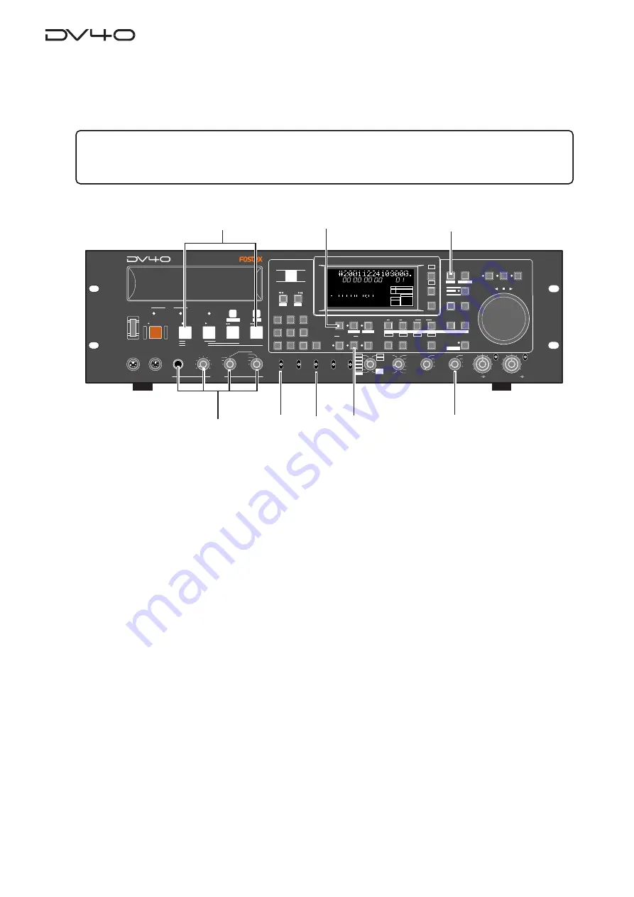
1. Set the [CONTROL] select switch to "LOCAL".
2. Set the [INPUT] select switch to "DIGITAL".
3. Select the digital input tracks using the "D. IN Tr?" menu in the Setup mode, if necessary.
The
"D. IN Tr?"
menu is initially set to
"Auto"
, in which the track numbers correspond to the input
numbers. See
"Chapter 11: Setup mode"
for details about the
"D. IN Tr?"
menu.
4. Set the [CLOCK] switch to "DIGITAL".
"DIGITAL"
and
"-EXT-"
light up in the
"CLOCK"
section on the display, showing that the system clock is
derived from the digital input signal.
If you wish to make the unit slaved to a video or word clock, select the
[CLOCK]
switch to
"VIDEO"
or
"WORD"
appropriately.
5. Press the [AUDIO READY - INSERT] key to turn on the INSERT indicator.
If you want to record timecode simultaneously, press the
[TC RDY]
key to turn on the indicator.
See
"Chapter 5: Timecode recording"
for details about time code recording.
6. Connect a pair of headphones to the [PHONES] jack, and set the monitor track selection switch to
"TR 1/TR 2".
7. Press the [INPUT MON] key to turn on the indicator.
You do not need to adjust the input level for digital recording.
You can check digital input levels from the level meters by activating the input monitor mode.
8. Press the [F FWD] key while holding down the [STOP] key to move to the record end point.
Recording
1. Press the [RECORD] key.
The unit starts recording.
2. After recording, press the [STOP] key to stop the unit.
If you are not satisfied with the result, undo the recording.
• Preparation for recording
Tips:
In the INSERT mode, recording is made to an existing audio file. Therefore, set the
[AUDIO FILE]
,
[TR MODE]
and
[SAMPLING FREQ]
switches to the appropriate positions that match the audio file.
If you set any of these switches inappropriately, the switch position name flashes on the display for warning.
SHUTTLE
JOG
VARI PITCH
IN
DST
OUT
symbol
SKIP/CURSOR
LOCATE
ENTER/YES
EXIT/NO
DISP
MARGIN
FILE SEL
STORE
AUDIO EDIT
UNDO
2
ABC
3
DEF
8
9
6
5
PQRS
TUV
WXYZ
GHI
JKL
MNO
TC RDY
IN
SLATE TONE
MUTE
INSERT
OPEN/CLOSE
0
7
4
1
RESET
TIME
LEVEL
MEMORY
CUE POINT
SETUP
NEW FILE
INPUT MON
MUTE REC
TONE REC
PREVIEW
HOLD
DIRECTORY
UTILITY
AUDIO RDY
TR1
SOURCE
OUT
space
BY-
PASS
ON
OFF
MIN
MAX
MAX
BY-
PASS
ON
OFF
MIN
VIDEO
WORD
INT
24H RUN
REC RUN
FREE RUN
EXT RUN
TR1
INPUT LEVEL
TR2
TR4
TR3
CLOCK
30DF
29.97
29.97DF
25
24
23.97
30
RSVD
PULL
48
44.1
48
(kHz)
192
44.1
16BIT
88.2
96
176.4
-0.1%
NORM
+0.1%
MULTI(4TR)
STEREO
MONO
DIGITAL
ANALOG
SDII
BWF
REMOTE
LOCAL
TC GEN MODE
CONTROL
UP/DOWN
SAMPLING FREQ
TR MODE
INPUT
AUDIO FILE
FRAME RATE
DV D M A S T E R R E C O R D E R
MONO
MAX
MIN
POWER
TR4
TR3
TR2
TR1,3+2,4
TR3+4
TR1+2
TR1
LOCATE REC END
LOCATE ABS 0
F FWD
REWIND
PLAY
STOP
RECORD
SOURCE PLAY
TC SETUP
LIST PLAY
CHASE
EDIT
PHONES
HD
DVD
DRIVE
KEYBOARD
MOUSE
DIGITAL
TR2
TR3
TR4
SHIFT
DISP
+
-
TAPE MODE
24BIT
H
M
S
F
2
1
-INT-
BWF
FORMAT
CLOCK
-0.1%
kHz
48
24
FS
BIT
PGM
ABS
∞
60
50
42
34
28
2018
12
8
6 5 4 3 2 1 0 OL
2
5
7
6
4
1
3
8
Summary of Contents for DV-40
Page 36: ...3 6 ...
Page 54: ...4 18 ...
Page 64: ...5 10 ...
Page 74: ...6 10 ...
Page 80: ...7 6 ...
Page 85: ...9 1 Chapter 9 Audio file management This chapter describes the management of audio files ...
Page 106: ...10 10 ...
Page 118: ...11 12 ...
Page 128: ...13 6 ...
Page 129: ...14 1 Chapter 14 Specifications ...
Page 169: ...35 DV40 Owner s Manual Version V1 2 Supplement Memo ...


