background image

10-9

6. Press the [EXIT/NO] or [STOP] key repeatedly to exit the AUDIO EDIT mode.

Tips:

If you are not satisfied with the result, you can undo the cut operation.
Note that, however, you cannot undo the cut operation with a 

"Tape mode"

 audio file.

Tips:

The cut track data still remains in the clipboard after the cut operation is completed.
While the cut data remains in the clipboard, you can paste or insert the data by executing

 "Clip Paste?"

or 

"Clip Insert?"

 described earlier in this chapter.

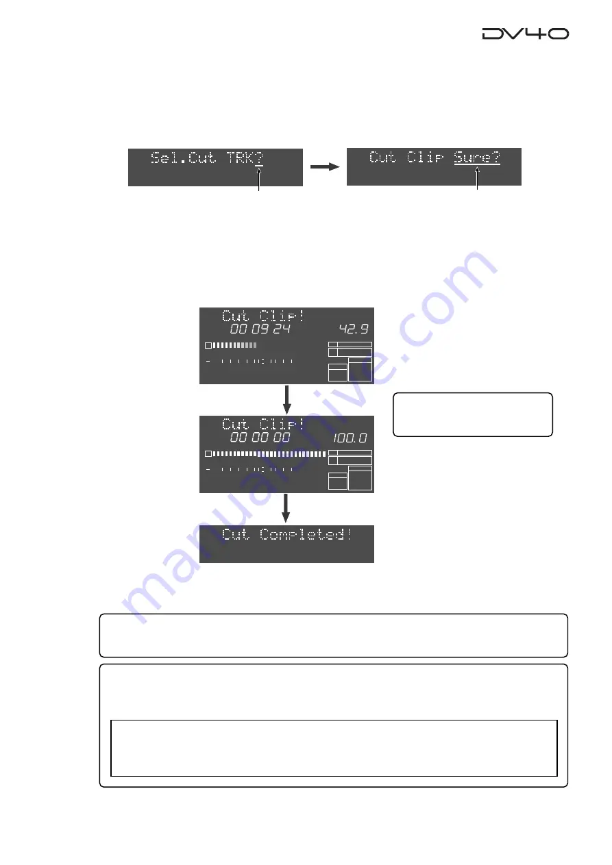
5. Press the [ENTER/YES] key.

The unit starts cutting track data between the 

"SOURCE IN"

 and 

"SOURCE OUT"

 points of the specified

track(s).

The display shows the required time together with the achieved percentage for cut.
The time is counted down while the percentage is counted up as the cut operation is in progress.
Also, the status is graphically shown by the track 1 level indicators which gradually light up from left to
right.  When all the data is cut, 

"Cut Completed!"

 is shown and the unit stops.

4. Press the appropriate edit point key(s) ([SOURCE IN], [SOURCE OUT], [DEST IN] or [DEST OUT] keys)

to select the track(s) to be cut, and press the [ENTER/YES] key.

* These edit point keys are used to select tracks 1 through 4 (TR 1 through TR 4), as labeled below the keys.

Depending on the track mode of the audio file, the selectable tracks are restricted.

By pressing the 

[ENTER/YES]

 key,

 "Cut Clip"

 (or 

"Cut"

 when selecting a 

"Tape mode"

 audio file) with flashing

"Sure?"

 appears on the display.

Flashing

H

M

S

2

1

-INT-

BWF

FORMAT

CLOCK

-0.1%

kHz

48

24

FS

BIT

REMAIN

60

50

42

34

28

2018

12

8

6 5 4 3 2 1 0 OL

%

H

M

S

2

1

-INT-

BWF

FORMAT

CLOCK

-0.1%

kHz

48

24

FS

BIT

REMAIN

60

50

42

34

28

2018

12

8

6 5 4 3 2 1 0 OL

%

<Note>

With a 

"Tape mode"

 audio file, the cut track data does not remain in the clipboard.

Therefore, if you are going to perform the paste or 

"SOURCE PLAY"

 function, 

"Empty Clipboard!"

appears and the operation is canceled.

Tips:

When a 

"Tape mode"

 audio file is

selected,

 "Cut!"

 appears.

Flashing

Summary of Contents for DV-40

Page 1: ...R4 TR3 CLOCK 30DF 29 97 29 97DF 25 24 23 97 30 RSVD PULL 48 44 1 48 kHz 192 44 1 16BIT 88 2 96 176 4 0 1 NORM 0 1 MULTI 4TR STEREO MONO DIGITAL ANALOG SDII BWF REMOTE LOCAL TC GEN MODE CONTROL UP DOWN SAMPLING FREQ TR MODE INPUT AUDIO FILE FRAME RATE DVD MASTER RECORDER MONO MAX MIN POWER TR4 TR3 TR2 TR1 3 2 4 TR3 4 TR1 2 TR1 LOCATE REC END LOCATE ABS 0 F FWD REWIND PLAY STOP RECORD SOURCE PLAY TC...

Page 2: ...ateral triangle is intended to alert the user to the presence of uninsulated dangerous voltage within the product s enclosure that may be of sufficient magnitude to constitute a risk of electric shock to persons The exclamation point within an equilateral triangle is intended to alert the user to the presence of important operating and maintenance servicing instructions in the literature accompany...

Page 3: ... analog source in the NEW FILE mode 4 3 Preparation 4 3 Preparation for recording 4 4 Recording 4 5 Playback of recorded audio 4 6 Multiple undo function 4 6 You can create an audio file before recording 4 7 Recording an analog source in the INSERT mode 4 8 Preparation for recording 4 8 Recording 4 8 Selecting a desired file on a disk 4 9 Recording to a Tape mode audio file in the INSERT mode 4 10...

Page 4: ...meric keys 6 4 Storing a time to locate memory CUE MEMORY 6 5 Storing a time to a locate point memory CUE or MEMORY point memory on the fly 6 6 Storing a time to a locate point using the numeric keys 6 7 Editing a name of CUE or MEMORY point 6 8 Clearing a CUE or MEMORY point memory 6 9 Chapter 7 Locate Function A variety of locate functions 7 2 Location to the beginning ABS 0 of an audio file 7 2...

Page 5: ...ta 10 2 Inserting track data 10 4 Erasing track data 10 6 Cutting track data 10 8 Chapter 11 Setup mode How to access and set a Setup menu 11 2 Display contrast setting 11 3 Reference level setting 11 3 Digital input track selection 11 3 Digital output signal format selection 11 3 Skipped item selection for the skip mode 11 4 Auto EE mode On Off 11 4 Self diagnoses On Off 11 4 Panel lock On Off 11...

Page 6: ...he running time 11 11 Chapter 12 Preview Function How to select a Utility menu 12 2 Selecting Rec Protect On or Off 12 3 Renumbering CUE points 12 3 Releasing undo files 12 4 Selecting On or Off of the resume function 12 4 Chapter 13 Importing an audio file to a computer Chapter 14 Specifications ...

Page 7: ...1 1 Chapter 1 Before using the DV40 Before using the DV40 you must carry out some preparations This chap ter describes how to set the internal clock and how to format a DVD RAM disk ...

Page 8: ... display showing the system clock followed by Disk Initialize the unit activates and scans the disk showing Scan Disk then shows No Disk Note When turning off the power make sure that the unit is not in the Setup mode and ceases disk access Y M D H M S DATE H M S F 4 3 2 1 INT BWF FORMAT CLOCK kHz 48 24 FS BIT PGM ABS 60 50 42 34 28 2018 12 8 6 5 4 3 2 1 0 OL ...

Page 9: ... the date time value appropriately according to the following methods Use the SKIP CURSOR I I keys to move the editing point and use the jog dial to enter the value or Use the numeric keys to enter the date time value directly When entering data using the numeric keys regardless of the current editing point the value is entered from the right hand second digit which moves left as additional digits...

Page 10: ... Disk Scan is shown as a flashing display while scanning it automatically recognizes that the disk is unformatted and enters the Format menu Format with flashing is shown You can format the disk by the following procedure in the next page REWRITABLE About usable DVD RAM disks TYPE 2 one side disks with 4 7 GB capacity can be used with the DV40 Flashing H M S F 4 3 2 1 INT BWF FORMAT CLOCK kHz 48 2...

Page 11: ...l mode No Audio Files is shown after formatting is completed On a Normal format disk a Normal mode audio file BWF or SDII is automatically created when executing recording in the NEW FILE mode Or you can also create Normal mode audio files us ing the file select function before recording Up to 200 audio files can be created Two Tape mode audio files BWF or SDII of ap proximately 2 GB each are auto...

Page 12: ...al mode No Audio Files appears showing that there is no audio file on the disk or After completing formatting a single Tape mode audio file is created with appropriate audio file format TR mode and sampling frequency according to the settings of the AUDIO FILE TR MODE and SAMPLING FREQ switches Also the TAPE MODE indicator red on the front panel is lit Note When formatting a used disk in the Tape ...

Page 13: ... in the Tape format mode The file format of the Tape mode files is determined by the AUDIO FILE switch setting when formatted The two Tape mode audio files are more tape like so you may regard as if there were two analog tapes on a disk If an accident such as a sudden power failure or shutdown of the unit may happens during recording data on a Tape mode audio file recorded before the accident will...

Page 14: ...dable time of the Tape mode audio file by following the operation below While a disk is stopped press the F FWD key while holding down the STOP key The current position moves to the end of the tape and the maximum recordable time of a Tape mode file with the track mode and sampling frequency bit length selected by the TR MODE and SAMPLING FREQ switches when formatted is shown on the display The ex...

Page 15: ...2 1 Chapter 2 Names and Functions This chapter describes names and functions of controls on the front panel as well as those of connectors on the rear panel ...

Page 16: ...1 kHz 44 1 88 2 176 4 192 DSD 96 32 48 24 32 20 16 FS BIT LEVEL MARGIN NEXT MB PGM CHASE RDY TC DIGITAL CHASE OFFSET UB GEN MEMORY ABS CUE LOCATE REMAIN DATE IN LTC SETUP 60 50 42 34 28 2018 12 8 6 5 4 3 2 1 0 OL TAPE MODE 24BIT 4dBu 10dBV 4dBu 10dBV 4dBu 10dBV 4dBu 10dBV TR4 TR2 TR3 TR1 TR3 TR1 BAL 4dBu BAL 4dBu UNBAL 10dBV UNBAL 10dBV TR4 TR2 BAL 4dBu BAL 4dBu UNBAL 10dBV UNBAL 10dBV OUTPUT THRU...

Page 17: ...he current currently selected drive is lit In the initial condition the DVD drive is selected If the optional HD drive is in stalled you can select the HD drive using the Drive Sel menu in the Utility mode See Chapter12 Utility mode for details 4 TAPE MODE indicator It is lit when a TAPE mode audio file is loaded See Chapter 1 Before using the DV40 for details about the format mode 5 CHASE TC SETU...

Page 18: ... Setup Utility and all sort of editing mode pressing this key exits the current mode Also pressing the PLAY REWIND or F FWD key while holding down this key executes the following STOP PLAY Plays back sound data on the clipboard and stops the recorder STOP REWIND Locates to ABS0 and stops the recorder STOP F FWD Locates to REC END and stops the recorder LOCATE REC END LOCATE ABS 0 F FWD REWIND PLAY...

Page 19: ...ing this key while holding down the STOP key locates the ABS 0 position the beginning position of the file 9 Monitor section a PHONES jack Connects headphones for monitoring b Headphones level control Adjust the level of headphones c Monitor track selection switch Selects tracks to be monitored from among 3 2 4 3 4 or 1 2 or selects MONO When selecting MONO you can select any mono track by using t...

Page 20: ...ARI PITCH IN DST OUT symbol SKIP CURSOR LOCATE ENTER YES EXIT NO DISP MARGIN FILE SEL STORE AUDIO EDIT UNDO 2 ABC 3 DEF 8 9 6 5 PQRS TUV WXYZ GHI JKL MNO TC RDY IN SLATE TONE MUTE INSERT OPEN CLOSE 0 7 4 1 RESET TIME LEVEL MEMORY CUE POINT SETUP NEW FILE INPUT MON MUTE REC TONE REC PREVIEW HOLD DIRECTORY UTILITY AUDIO RDY TR1 SOURCE OUT space BY PASS ON OFF MIN MAX MAX BY PASS ON OFF MIN VIDEO WOR...

Page 21: ...nd Utility modes 18 FILE SEL DIRECTORY key This key has primary unSHIFTed and secondary SHIFTed functions When unSHIFTed Pressing this key while stopped enters the File select mode in which you can select an audio file or create a new file in the directory SDII or BWF the current file belongs to When SHIFTed Pressing this key while stopped enters the Directory mode in which you can select an audio...

Page 22: ...play mode pressing this key enters the memory edit mode in which you can edit memory point data Pressing this key after pressing the STORE key stores the holding time to a memory point 99 memory points 01 through 99 are available You can give a name for each point Note that memory points 01 through 03 are fixed and the rest 04 through 99 are user memory points See Chapter 6 Storing time data for d...

Page 23: ...s overwritten each time you press the key 31 DEST IN PREVIEW TR 3 key This key has primary unSHIFTed and secondary SHIFTed functions When unSHIFTed Displays time data stored in this key so that you can edit the data Pressing this key after pressing the STORE key stores the holding time or edited time to the DEST IN point When editing track data this key selects track 3 When SHIFTed Pressing this k...

Page 24: ...cords the slate tone for the time set by the Tone Rec menu in the Setup mode and then continues normal recording When the INSERT mode is active pressing this key while stopped records the slate tone for the time set by the Tone Rec menu in the Setup mode and then stops 38 AUDIO RDY INSERT key Pressing this key alternates on and off of the INSERT mode When the mode is active you can turn on TC RDY ...

Page 25: ...plays a file name menu title etc b Displays time data system clock date etc c Displays the quantization bit number of the cur rent audio file If it does not match the setting of the SAMPLING FREQ switch on the front panel the bit number that matches the switch setting flashes d Displays the sampling frequency of the current audio file If it does not match the setting of the SAMPLING FREQ switch on...

Page 26: ... to 4 tracks of playback Up to 2 tracks of recording up to 4 tracks of playback Up to 2 tracks of playback only Up to 2 tracks of playback only 49 FRAME RATE switch Selects the frame rate for recording playback and internal TC generator OPTION 23 976 24 25 29 97DF 29 97 30DF 30 American motion picture 0 1 American motion picture European film PAL SECAM video EBU NTSC color with real time adjust NT...

Page 27: ...ster WORD flashes on the display which lights steadily when the unit locks to the word clock DIGITAL The external video clock is the master VIDEO flashes on the display which lights steadily when the unit locks to the video clock The external clock available in the digital sig nal received via the DIGITAL INPUT con nector is the master DIGITAL flashes on the display which lights steadily when the ...

Page 28: ...RU THRU OUTPUT AC IN 1 GND 2 HOT 3 COLD 1 GND 2 HOT 3 COLD 1 GND 2 HOT 3 COLD 15P REMOTE 9P REMOTE GPI DIGITAL OUTPUT WORD TIME CODE ETHERNET ANALOG INPUT BALANCED ANALOG OUTPUT DIGITAL INPUT VIDEO 1 2 3 4 5 6 7 8 9 10 11 4dBu 10dBV 4dBu 10dBV 4dBu 10dBV 4dBu 10dBV TR4 TR2 TR3 TR1 TR3 TR1 BAL 4dBu BAL 4dBu UNBAL 10dBV UNBAL 10dBV TR4 TR2 BAL 4dBu BAL 4dBu UNBAL 10dBV UNBAL 10dBV 1 GND 2 HOT 3 COLD...

Page 29: ...X RX When data is transmitted or and received this indicator is lit INPUT 75Ω ON OFF THRU VIDEO A B C INPUT 75Ω ON OFF THRU OUTPUT WORD A B C D A VIDEO INPUT connector Accepts a video clock signal Connector BNC type B 75É ON OFF switch To terminates the video clock set this switch to ON C VIDEO THRU connector Echoes an incoming video signal Connector BNC type A WORD INPUT connector Accepts a word ...

Page 30: ...e Ground Frame Ground NC NC NC NC NC 12V Transmit A Receive B Receive Common Spare Transmit Common Transmit B Receive A Transmit A Receive B Receive Common Spare Transmit Common Transmit B Receive A Receive A Transmit B Transmit Common Spare Receive Common Receive B Transmit A T R A B A and B in the table above are defined as follows Use a straight cable A B 1 Mark B A 0 Space B GPI OUTPUT connect...

Page 31: ...3 1 Chapter 3 Reformatting optimizing a disk This chapter describes how to reformat a formatted disk and optimize a disk ...

Page 32: ...8 6 5 4 3 2 1 0 OL 2 1 INT BWF FORMAT CLOCK 0 1 kHz 48 24 FS BIT 60 50 42 34 28 2018 12 8 6 5 4 3 2 1 0 OL 2 1 INT BWF FORMAT CLOCK 0 1 kHz 48 24 FS BIT 60 50 42 34 28 2018 12 8 6 5 4 3 2 1 0 OL 4 Press the ENTER YES key again The display shows the following and now you can edit the volume name of the disk which is tentatively named DV40 DVD See the next Tips about how to edit a volume name althou...

Page 33: ...4 3 2 1 0 OL 2 1 INT BWF FORMAT CLOCK 0 1 kHz 48 24 FS BIT 60 50 42 34 28 2018 12 8 6 5 4 3 2 1 0 OL When selecting Norm The display scrolls If enter key is pushed will start formatting and delete DVD area data Are you sure When selecting Tape The display shows Disk Type with flashing New for selecting disk type Select Used using the jog dial and then go to the next step Flashing Flashing Note Whe...

Page 34: ...018 12 8 6 5 4 3 2 1 0 OL SDII audio file BWF audio file 7 Press the ENTER YES key 2 1 INT BWF FORMAT CLOCK 0 1 kHz 48 24 FS BIT 60 50 42 34 28 2018 12 8 6 5 4 3 2 1 0 OL H M S F 2 1 INT BWF FORMAT CLOCK 0 1 kHz 48 24 FS BIT PGM ABS 60 50 42 34 28 2018 12 8 6 5 4 3 2 1 0 OL If you reformat the disk in the Norm mode the formatting is completed quickly and Fmt Completed is shown followed by No Audio...

Page 35: ...0 1 kHz 48 24 FS BIT 60 50 42 34 28 2018 12 8 6 5 4 3 2 1 0 OL 2 1 INT BWF FORMAT CLOCK 0 1 kHz 48 24 FS BIT REMAIN 60 50 42 34 28 2018 12 8 6 5 4 3 2 1 0 OL 5 Press the EXIT NO or STOP key The unit quits the Utility mode and the display shows the previous screen before entering the Utility mode Flashing The number is counted down as optimizing is in progress Note After optimizing a disk you canno...

Page 36: ...3 6 ...

Page 37: ...4 1 Chapter 4 Audio recording playback This chapter describes the basic audio recording playback for both analog and digital mute recording slate tone recording cueing by the jog shuttle mode etc ...

Page 38: ...it Multi 4 96kHz 24Bit Multi 4 176 4kHz 24Bit Multi 4 192kHz 24Bit Multi 4 Recording capabilities Playback capabilities The table below shows the recording and playback capabilities depending on the recording conditions Fs Bit length and the number of tracks and the DVD RAM disk capacity About the NEW FILE and INSERT mode About the expression for audio files in this manual As described in chapter ...

Page 39: ...10dBV 4dBu 10dBV 4dBu 10dBV TR4 TR2 TR3 TR1 TR3 TR1 BAL 4dBu BAL 4dBu UNBAL 10dBV UNBAL 10dBV TR4 TR2 BAL 4dBu BAL 4dBu UNBAL 10dBV UNBAL 10dBV OUTPUT THRU INPUT VGA VIDEO 10 100 LINK TX RX TR4 3 TR2 1 TR2 TR1 TR1 TR2 1 GND 2 HOT 3 COLD 192kHz 176 4kHz INPUT OUTPUT INPUT 75Ω ON OFF INPUT 75Ω ON OFF TR4 3 TR2 1 TR2 TR1 THRU THRU OUTPUT AC IN 1 GND 2 HOT 3 COLD 1 GND 2 HOT 3 COLD 1 GND 2 HOT 3 COLD ...

Page 40: ...h is defaulted to Off you can set the condition in which the input source can be monitored automatically See Chapter 11 Setup mode Tips BYPASS switch By setting the BYPASS switches beside the INPUT LEVEL controls to ON the INPUT LEVEL controls are disabled SHUTTLE JOG VARI PITCH IN DST OUT symbol SKIP CURSOR LOCATE ENTER YES EXIT NO DISP MARGIN FILE SEL STORE AUDIO EDIT UNDO 2 ABC 3 DEF 8 9 6 5 PQ...

Page 41: ...ed to the unit So you can use the margin display function instead of setting the peak hold time to infinity You can reset the current margin value by pressing the MARGIN RESET key Using the DISP LEVEL key you can choose what is shown on the display among the margin level track level and time the peak value is hold Notes for level adjustment Set the recording level with the INPUT MON indicator lit ...

Page 42: ...pleted The display changes to show the beginning of the audio file Flashing Notes for performing the multiple undo function You cannot undo recording on a Tape mode audio file The ending date time of each take is memorized based on the internal clock therefore it is important to adjust the date time of the internal clock correctly The unit keeps all takes on the disk in order to make the multiple ...

Page 43: ...file exists the audio file number currently selected starts flashing By rotating the jog dial in this condition you can bring up New File with flashing on the display where is one greater than the number of the existing audio files In the display examples on the right the number 01 file is selected The new file number is 03 because two audio files exist on the disk 3 Press the ENTER YES key A new ...

Page 44: ...apter 5 Timecode recording for details about time code recording 5 Connect a pair of headphones to the PHONES jack and set the monitor track selection switch to TR 1 TR 2 6 Press the INPUT MON key to turn on the indicator and use the INPUT LEVEL TR 1 andTR 2 controls to adjust the input levels of tracks 1 and 2 See Tips on page 4 5 for details about the input level adjustment 7 Press the F FWD key...

Page 45: ... an SDII file when a BWF file is currently selected set the AUDIO FILE switch to SDII In the FORMAT section on the display BWF is lit while SDII flashes 2 Press the FILE SEL key while stopped The current file number starts flashing 3 Rotate the jog dial to select a desired file number and press the ENTER YES key You can select from among files of the selected file type in step 1 above For example ...

Page 46: ...ng time You can check the maximum recording time by pressing the F FWD key while holding down the STOP key You can record to a Tape mode audio file when either one of the displays below is shown The recording procedure is same as described in Recording an analog source in the INSERT mode on page 4 8 or BWF audio file SDII audio file Tips Multiple punch in out With a Tape mode audio file you can pe...

Page 47: ... You cannot create another Tape mode audio file on a disk formatted in the Tape mode however you can create Normal mode audio files on the same disk 1 While a Tape mode audio file is selected press the FILE SEL key The current Tape mode file number 02 flashes 2 Rotate the JOG dial to show New File with the flashing file number Depending on whether you change the AUDIO FILE switch setting or not be...

Page 48: ... 4dBu BAL 4dBu UNBAL 10dBV UNBAL 10dBV OUTPUT THRU INPUT VGA VIDEO 10 100 LINK TX RX TR4 3 TR2 1 TR2 TR1 TR1 TR2 1 GND 2 HOT 3 COLD 192kHz 176 4kHz INPUT OUTPUT INPUT 75Ω ON OFF INPUT 75Ω ON OFF TR4 3 TR2 1 TR2 TR1 THRU THRU OUTPUT AC IN 1 GND 2 HOT 3 COLD 1 GND 2 HOT 3 COLD 1 GND 2 HOT 3 COLD 15P REMOTE 9P REMOTE GPI DIGITAL OUTPUT WORD TIME CODE MONITOR ETHERNET ANALOG INPUT BALANCED ANALOG OUTP...

Page 49: ...0 Press the INPUT MON key to turn on the indicator You do not need to adjust the input level for digital recording You can check digital input levels from the level meters by activating the input monitor mode Recording 1 Press the RECORD key New File appears for a short time on the display and the unit starts recording on the newly created file 2 After recording press the STOP key to stop the unit...

Page 50: ...wn the STOP key to move to the record end point Recording 1 Press the RECORD key The unit starts recording 2 After recording press the STOP key to stop the unit If you are not satisfied with the result undo the recording Preparation for recording Tips In the INSERT mode recording is made to an existing audio file Therefore set the AUDIO FILE TR MODE and SAMPLING FREQ switches to the appropriate po...

Page 51: ...or between songs while stopped This operation is possible only in the INSERT mode The following assumes that the audio file is stopped at the beginning ABS 0 or at the end of the last recording 1 Press the AUDIO RDY INSERT key to turn on the INSERT indicator 2 Press the SHIFT key to turn on the SHIFT indicator 3 Press the MUTE key to turn on the MUTE indicator The unit performs mute recording for ...

Page 52: ...possible only in the INSERT mode The following assumes that the audio file is stopped at the beginning ABS 0 or at the end of the last recording 1 Press the AUDIO RDY INSERT key to turn on the INSERT indicator 2 Press the SHIFT key to turn on the SHIFT indicator 3 Press the SLATETONE key to turn on the SLATE TONE indicator The unit performs slate tone recording for a duration set by the Slate tone...

Page 53: ...rmal speed While searching the appropriate or indicator above the jog dial is lit according to the rotating direction 3 To quit the shuttle mode press any of the transport keys the STOP key etc If the cueing position comes to the ABS 0 or REC END point the recorder automatically quits the shuttle mode and stops Cueing high speed shuttle by the shuttle function Using the shuttle function you can pe...

Page 54: ...4 18 ...

Page 55: ...5 1 Chapter 5 Timecode recording This chapter describes how to record timecode generated by the internal timecode gen erator or external timecode ...

Page 56: ...eously When recording audio and timecode while creating a new file Use the NEW FILE mode When recording audio and timecode to an existing file Use the INSERT mode Selecting the recording mode Two timecode sources to be recorded are available Timecode generated by the internal timecode generator External timecode received from theTIME CODE INPUT connector Selecting source timecode Note Timecode is ...

Page 57: ...disk is not striped from the beginning to the end Only the offset between the ABS time and timecode at the recording start point is recorded Therefore if you record a discontinuous timecode value in the middle the unit cannot recog nize it Also the user bit when timecode starts recording is valid throughout the timecode so the unit cannot handle the user bit that changes in the middle 1 Set the FR...

Page 58: ...L 10dBV UNBAL 10dBV OUTPUT THRU INPUT VGA VIDEO 10 100 LINK TX RX TR4 3 TR2 1 TR2 TR1 TR1 TR2 1 GND 2 HOT 3 COLD 192kHz 176 4kHz INPUT OUTPUT INPUT 75Ω ON OFF INPUT 75Ω ON OFF TR4 3 TR2 1 TR2 TR1 THRU THRU OUTPUT AC IN 1 GND 2 HOT 3 COLD 1 GND 2 HOT 3 COLD 1 GND 2 HOT 3 COLD 15P REMOTE 9P REMOTE GPI DIGITAL OUTPUT WORD TIME CODE MONITOR ETHERNET ANALOG INPUT BALANCED ANALOG OUTPUT DIGITAL INPUT VI...

Page 59: ...TC Setup mode details H M S F SF CHASE OFFSET Flashing To enter theTC Setup mode 1 Press the SHIFT key to turn on the indicator then press the CHASE TC SETUP key The unit enters the TC Setup mode and the display shows a menu The first time the unit enters the TC Setup mode after turning on the power the Chase Offset menu is shown Otherwise the display shows the menu previously selected H M S F SF ...

Page 60: ...eric keys to enter a numeric value When using the jog dial to enter a value you can move the flashing digit to be edited by using the keys When using the numeric keys to enter a time value each number is entered from the right digit which moves left as additional digits are entered You can enter up to 23H 59M 59S F in which is one smaller than the frame rate number 4 After entering the time press ...

Page 61: ...orded timecode on the disk is output from the TOME CODE OUTPUT connector Gen The timecode generated by the internal TC generator is output from the TOME CODE OUTPUT connector H M S F SF CHASE OFFSET H M S F SF CHASE OFFSET 3 Use the jog dial or numeric keys to enter a offset value When using the jog dial to enter a value you can move the flashing digit to be edited by using the keys When using the...

Page 62: ... it now can be edited Trimming the chase offset You can trim the chase offset set by the procedure described above in Editing the chase offset H M S F SF CHASE OFFSET H M S F SF CHASE OFFSET 3 Use the jog dial or numeric keys to trim the value You can trim the value in sub frame unit between 59s f 99sf and 59s f 99sf in which is one smaller than the frame rate number After trimming the value do no...

Page 63: ...he selected chase made is set and the display returns to show ChaseMD 4 To exit theTC Setup mode press the EXIT NO key or the STOP key 1 Use the jog dial or keys to select Chase MD The current chase mode is shown 2 Press the ENTER YES key The current chase mode starts flashing Tips To make the unit chase to the reference timecode press the CHASE key to activate the chase mode When activating the c...

Page 64: ...5 10 ...

Page 65: ...6 1 Chapter 6 Storing time data This chapter explains how to store time data to location memories for the track editing or locate functions ...

Page 66: ...or copy operation End point of a copy clip for insert operation End point of a erase clip for erase operation End point of a cut clip for cut operation Paste start point for paste operation Insert start point for insert operation DEST OUT memory for Auto Edit operation when controlling the unit via the RS422 P2 protocol CUE points 01 through 99 for location MEMORY points 00 through 99 for location...

Page 67: ... an edit point memory required for track edit ing There are two methods for enter a time on the fly and numerical entry H M S F SF 2 1 INT BWF FORMAT CLOCK 0 1 kHz 48 24 FS BIT NEXT ABS CUE 60 50 42 34 28 2018 12 8 6 5 4 3 2 1 0 OL Note You must always set an IN point earlier than the corresponding OUT point i e SOURCE IN SOURCE OUT DEST IN DEST OUT Tips The display example shown above is used to ...

Page 68: ... digits the unit automatically calculates and set the proper time For example if you enter 00H 12M 75S 00F 00SF the stored time value is 00H 13M 15S 00S 00SF 2 Enter the desired time There are two methods for time entry as below 3 Press the STORE key Select Memories is shown on the display as in step 2 on the previous page Ignore the display and go to the next step 4 Press a desired edit point key...

Page 69: ...int time to a locate point memory and use it to locate there later You can also give desired names to them or clear the data In the same way as with edit point memories there are two methods for storing a time data to a locate point memory on the fly and numerical entry Tips If you change the current audio file to another one and store a time to a new MEMORY point the MEMORY point numbers used in ...

Page 70: ... bank and the display returns to the previous screen Tips If you store another time data to a locate point memory in the newly selected bank you do not need to press the appropriate key twice 3 2 To store the time data to a locate point memory in the bank which is not currently selected press the appropriate locate point key MEMORY or CUE POINT key twice Pressing the key for the first time switche...

Page 71: ...ial to enter a value If the value of the edit point overruns or underruns the value of the left digit increments or decrements respectively Use the numeric keys to enter a time directly Each number is entered from the right digit which moves left as additional digits are entered For example to enter 00H 12M 15S 00F 00SF press 0 0 1 2 1 5 0 0 0 0 3 After completing time entry press the ENTER YES ke...

Page 72: ...2 34 28 2018 12 8 6 5 4 3 2 1 0 OL Flashing 3 Press the MARGIN RESET CLR key repeatedly until all characters are deleted Each press of the MARGIN RESET CLR key deletes a left hand character and moves the character string to the left When all characters are deleted _ flashes H M S F SF 2 1 INT BWF FORMAT CLOCK 0 1 kHz 48 24 FS BIT ABS CUE 60 50 42 34 28 2018 12 8 6 5 4 3 2 1 0 OL Flashing 4 Use the...

Page 73: ...or MEMORY key three times CUE Delete is shown with flashing Sure H M S F SF 2 1 INT BWF FORMAT CLOCK 0 1 kHz 48 24 FS BIT ABS CUE 60 50 42 34 28 2018 12 8 6 5 4 3 2 1 0 OL Flashing H M S F SF 2 1 INT BWF FORMAT CLOCK 0 1 kHz 48 24 FS BIT ABS CUE 60 50 42 34 28 2018 12 8 6 5 4 3 2 1 0 OL Flashing 3 Press the ENTER YES key The selected locate point memory is cleared and the display returns to the No...

Page 74: ...6 10 ...

Page 75: ...ate functions This chapter describes various locate functions including direct location to the beginning or end of an audio file location to a locate or edit point and skip location between locate points or audio files ...

Page 76: ...P key The recorder locates to the beginning ABS0 of the current audio file and the display shows ABS 00H 00M 00S 00F LOCATE REC END LOCATE ABS 0 F FWD REWIND PLAY STOP RECORD SOURCE PLAY Location to the end REC END of the current audio file Regardless of the current position you can locate to the end REC END of the current audio file 1 When the recorder is stopped press the E FWD key while holding...

Page 77: ... In is shown as MEMORY 02 holds time data of the point where recording started last time H M S F SF MEMORY ABS 2 Press the LOCATE key The recorder locates to the MEMORY 02 point and the display returns to the Normal screen Each time you make recording the MEMORY 02 point is overwritten Location to the last recording end position You can locate to the point between ABS 0 and REC END where recording...

Page 78: ...ay returns to the Normal screen Tips You can edit the time shown on the display after carrying out step 1 above By pressing the LOCATE key after editing the time you can locate to the edited time See Chapter 6 Storing time data for details about how to edit time data Location to a CUE point By specifying a desired CUE point memory among 01 through 99 you can locate to the point 1 When the recorder...

Page 79: ...ou can locate to a CUE or MEMORY point quickly 1 Set the Skip Mode menu in the Setup mode to CUE or MEM The Skip Mode menu is initially set to FILE See Chapter 11 Setup mode for details 2 Press SKIP CURSOR or key Each time you press the key the display shows something like the examples below and the recorder locates the next or previous locate point CUE or MEMORY point depending on the selection i...

Page 80: ...7 6 ...

Page 81: ...8 1 Chapter 8 Preview function This chapter describes the fade in fade out preview function at the edit or lo cate points assigned to the location memory keys ...

Page 82: ...peaker or headphones while the level meter indicators runs from left to right H M S F SF 4 3 2 1 INT SDII FORMAT CLOCK kHz 48 24 FS BIT MEMORY 60 50 42 34 28 2018 12 8 6 5 4 3 2 1 0 OL H M S F SF 4 3 2 1 INT SDII FORMAT CLOCK kHz 48 24 FS BIT MEMORY 60 50 42 34 28 2018 12 8 6 5 4 3 2 1 0 OL Display example of the fade in preview at the SOURCE IN point Display example of the fade out preview at the...

Page 83: ...ade in preview at the selected point During preview the level meter indicators runs from left to right H M S F SF 2 1 INT BWF FORMAT CLOCK 0 1 kHz 48 24 FS BIT MEMORY ABS 60 50 42 34 28 2018 12 8 6 5 4 3 2 1 0 OL H M S F SF 2 1 INT BWF FORMAT CLOCK 0 1 kHz 48 24 FS BIT MEMORY ABS 60 50 42 34 28 2018 12 8 6 5 4 3 2 1 0 OL H M S F SF 4 3 2 1 INT BWF FORMAT CLOCK kHz 48 24 FS BIT MEMORY 60 50 42 34 2...

Page 84: ...ut of the preview playback area Void Data appears on the display When it appears you cannot continue preview therefore move back the point to the playback area 1 Start preview by following the procedure shown in the previous page 2 Use the jog dial to trim the point during preview You can trim the point in subframe unit 3 After trimming press the ENTER YES key The trimmed time data is stored to th...

Page 85: ...9 1 Chapter 9 Audio file management This chapter describes the management of audio files ...

Page 86: ... SDII file 01 is stored in the sd2f directory 5 Press the ENTER YES key Audio file 01 is created and the display shows the tentative file name as well as the ABS 0 time the beginning of the file The tentative name begins by S or B which shows the file format S for SDII and B for BWF selected by the AUDIO FILE switch in step 1 above followed by the time and date when the file is created The display...

Page 87: ...eate another audio file regardless of whether the currently selected audio file is Tape mode or Normal mode carry out steps 1 through 4 above and then use the jog dial to show New File followed by pressing the ENTER YES key 1 Select a desired audio file format between BWF and SDII using the AUDIO FILE switch 2 Select a desired track mode using the TR MODE switch 3 Select a desired sampling frequen...

Page 88: ... as you keep this setting you can carry out the file selection using the skip function If the Skip Mode menu is set to CUE or MEM change the option to File See Chapter 11 Setup mode for details about how to set the Skip Mode menu 1 While stopped press the SKIP CURSOR or key Pressing the key skips to the beginning of the previous audio file while pressing the key skips to the beginning of the next ...

Page 89: ... point When pressing another numeric key the flashing point moves to the right 4 Press the MARGIN RESET CLR key repeatedly until all the characters shown are deleted Each press of the key deletes the leftmost character and moves the rest of the characters left 3 Use the jog dial to select the File Name Edit menu and press the ENTER YES key The current file name is shown in which the leftmost chara...

Page 90: ...u delete all files in the directory bwff or sd2f No Audio File is shown 3 Use the jog dial to select the Delete File menu and press the ENTER YES key Sure flashes to confirm deleting the current file To cancel deleting press the EXIT NO key while Sure flashing 4 Press the ENTER YES key The audio file is deleted The display shows Completed momentarily followed by the ABS 0 point the beginning of th...

Page 91: ...s the ENTER YES key If there is more than one deleted audio file you can select a desired file using the jog dial Pressing the ENTER YES key restores the file immediately and the display shows Completed followed by Restore DelFile 5 Press the EXIT NO or STOP key to exit the Utility mode The display shows ABS 0 the beginning of the restored file Tips The restored file is numbered the same as before...

Page 92: ... and press the ENTER YES key Sure flashes on the display To stop duplication press the EXIT NO key while Sure flashes 2 Press the ENTER YES key The unit starts duplication of the current file The display shows the required time for duplicating the file which is counted down while duplication is in progress When completed Dupl completed is shown on the display 3 Press the EXIT NO or STOP key The un...

Page 93: ...SDII to BWF or BWF to SDII is shown with flashing Sure on the display To stop conversion press the EXIT NO key while Sure flashes 2 Press the ENTER YES key The unit starts converting the file format SDII to BWF or vice versa The display shows the required time for converting the file format which is counted down while the conversion is in progress When completed Conv completed is shown on the disp...

Page 94: ... File Notes When creating a new MONO file if a file with the same name already exists in the disk Already existence same file name Are you sure is shown repeatedly If you are going to divide a MONO file Void appears and the unit ignores the operation If there is not enough disk space for dividing an audio file and creating MONO files Disk Volume Over is shown and the unit does not execute the oper...

Page 95: ...mbined file type between ST and 4TR Track 1 Track 2 Track 1 Track 2 Stereo mode File MONO mode File Track 1 Track 2 Track 3 Track 4 Track 1 Track 2 Track 3 Track 4 Multi mode File MONO mode File 3 Use the jog dial to select ST and press the ENTER YES key The display shows the screen in which you can select a MONO file assigned to track L 4 Use the jog dial to select a file assigned to track L and ...

Page 96: ... display shows the screen in which you can select a MONO file assigned to track 2 5 Use the jog dial to select a file assigned to track 2 and press the ENTER YES key The display shows the screen in which you can select a MONO file assigned to track 3 6 Use the jog dial to select a file assigned to track 3 and press the ENTER YES key The display shows the screen in which you can select a MONO file ...

Page 97: ...10 1 Chapter 10 Editing track data This chapter describes how to edit track data using the paste insert cut and erase functions ...

Page 98: ...lect the copy source track s and press the ENTER YES key These edit point keys are used to select tracks 1 through 4 TR 1 through TR 4 as labeled below the keys Depending on the track mode of the audio file the selectable tracks are restricted see the note above Pressing the ENTER YES key copies data to the clipboard immediately The display shows Completed momentarily followed by Clip Paste Note t...

Page 99: ...radually light up from left to right When all the data is pasted Paste Completed is shown and the unit stops Flashing 8 Press the EXIT NO or STOP key repeatedly to exit the AUDIO EDIT mode Tips If you are not satisfied with the result you can undo the paste operation Note that however you cannot undo the paste operation with a Tape mode audio file Tips SOURCE PLAY You can monitor the track data co...

Page 100: ...ricted see the note above Pressing the ENTER YES key copies data to the clipboard immediately The display shows Completed momentarily followed by Clip Paste Flashing Tips The REC END point of the track which data is inserted to moves forward Sound data A Sound data A SOURCE IN point SOURCE OUT point DEST IN point Note You cannot carry out the insert operation with a Tape mode audio file Note The s...

Page 101: ...cified track s from the DEST IN point The display shows the required time together with the achieved percentage for insert The time is counted down while the percentage is counted up as the insert operation is in progress Also the status is graphically shown by the track 1 level indicators which gradually light up from left to right When all the data is inserted Insert Completed is shown and the u...

Page 102: ... keys to select the track s to be erased and press the ENTER YES key These edit point keys are used to select tracks 1 through 4 TR 1 through TR 4 as labeled below the keys The selected track number s surrounding by a box flash es in red By pressing the ENTER YES key Erase Clip or Erase when selecting a Tape mode audio file with flashing Sure appears on the display Flashing Tips The erase operatio...

Page 103: ...rase operation with a Tape mode audio file Tips The erased track data still remains in the clipboard after the erase operation is completed To check the erased track data press the PLAY key while holding down the STOP key to perform the SOURCE PLAY function While the erased data remains in the clipboard you can paste or insert the erased data by executing Clip Paste or Clip Insert described earlie...

Page 104: ...nuous timecode Note If only data on a single track of a STE REO audio file is cut the REC END point of the file does not changed For example if only data on track 2 is cut as illustrated on the right the REC END point of the audio file does not changed because the REC END point of track 1 does not change Cut data SOURCE IN point SOURCE OUT point REC END REC END REC END Cut data REC END Track 2 Tra...

Page 105: ...ich gradually light up from left to right When all the data is cut Cut Completed is shown and the unit stops 4 Press the appropriate edit point key s SOURCE IN SOURCE OUT DEST IN or DEST OUT keys to select the track s to be cut and press the ENTER YES key These edit point keys are used to select tracks 1 through 4 TR 1 through TR 4 as labeled below the keys Depending on the track mode of the audio...

Page 106: ...10 10 ...

Page 107: ...ck selection 5 Digital output signal format selection 6 Skipped item selection for the skip mode 7 Self diagnoses on off 8 Auto EE mode on off 9 Panel lock on off 10 Peak hold time setting 11 GPI on off 12 Slate tone recording time 13 Mute recording time 14 Saving setup data to a User box 15 Loading setup data from a User box 16 TCP IP settings 17 Main CPU version display 18 Ethernet version displ...

Page 108: ... indicator is unlit 1 While the unit is stopped and the SHIFT indicator is unlit press the SETUP key The unit enters the Setup mode The first time the unit enters the Setup mode after turning on the power the first level of the RTC Adjust menu is shown on the display Otherwise the first level of the Setup menu previously accessed is shown SETUP Y M D H M S SETUP 2 Use the jog dial to select a desi...

Page 109: ...t sig nals at the same time while the selected tracks record digital input signals This setting is dependent on files and is maintained after you turn off the power You can save or load the setting Digital output signal format selection SETUP SETUP SETUP SETUP You can control the display contrast via the Con trast menu This setting is global and is not dependent on files The setting is maintained ...

Page 110: ...BS time 00 00 12 Rec time out error ABS time 00 00 23 Rec time out error ABS time 00 00 37 Rec time out error ABS time 00 00 45 Rec time out error You can select the item to be skipped in the skip mode This setting is dependent on files and is maintained after you turn off the power You can save or load the setting Skipped item selection for the skip mode File CUE Skips through audio files current...

Page 111: ...you turn off the power You can save or load the setting GPI on off SETUP Off On The GPI function is deactivated This is the default The GPI function is activated Pin 1 Pin 2 Pin 3 Pin 4 Pin 5 GND STOP PLAY Feeding the low pulse signal is equivalent to pressing the STOP key Feeding the low pulse signal is equivalent to pressing the PLAY key Feeding the low pulse signal is equivalent to pressing the...

Page 112: ...t User Setup Save and press the ENTER YES key Now you can select a User Box to which the data is saved The first time you enter this menu BoxNo1 User1 is shown where 1 is flashing as below User1 is the tentative name SETUP SETUP While the display above is shown you can select a User Box from among Box numbers 1 through 9 by using the jog dial or the keys If you select any of Box numbers 2 through ...

Page 113: ...gain The unit immediately loads the data and shows Completed followed by User Setup Load SETUP SETUP 2 Select a desired box and press the ENTER YES key Sure flashes on the display shows the selected box number SETUP SETUP SETUP 6 To exit the Setup mode press the EXIT NO key or the STOP key Loading setup data You can load a setup data box from among the default box Box number 0 and user boxes Box n...

Page 114: ...r of the screen above is shown press the ENTER YES key The leftmost three digit value of the current IP address starts flashing showing that you can now edit it TCP IP settings You can set parameters for the TCP IP By selecting the TCP IP Setup menu and pressing the ENTER YES keys the IP address setting sub menu is shown SETUP The following description assumes that each sub menu is already selecte...

Page 115: ... exit the Setup mode press the EXIT NO key or STOP key SETUP SETUP SETUP Showing the router IP address 1 Select Gateway and press the SKIP CURSOR key The current IP address is shown the default is 192 168 1 1 Pressing the or key alternates the following screens SETUP Setting the router IP address 1 While either of the screen above is shown press the ENTER YES key The leftmost three digit value of ...

Page 116: ...nt name is cleared Use the jog dial or numeric keys to enter the desired alphanumeric character and use the keys to move the editing point 3 After entering the desired name press the ENTER YES key The new log in name is set and the display shows the screen for entering a password the default is fostex SETUP Flashing SETUP SETUP 4 Enter the desired password using the same method as step 2 above Up ...

Page 117: ...rnet software version You can check the ethernet software version of the unit by selecting Version Ethernet When you have any trouble or question and contact our service section you may be asked the ethernet software version Showing the running time You can check the running of the unit by selecting Running Time When you have any trouble or question and contact our service section you may be asked...

Page 118: ...11 12 ...

Page 119: ...f 2 Resume On Off 3 CUE Renumbering 4 Releasing undo files 5 Editing a file name See Chapter 9 Audio file management 6 Deleting an audio file See Chapter 9 Audio file management 7 Restoring a deleted file See Chapter 9 Audio file management 8 Formatting a disk See Chapter 3 Reformatting optimizing a disk 9 Optimizing a disk See Chapter 3 Reformatting optimizing a disk This chapter describes detail...

Page 120: ...r turning on the power the first level of the Rec Protect menu appears Or if it is not the first time the unit enters the Utility mode after turning on the power the first level of the previously selected menu appears 3 Rotate the jog dial or use the SKIP CURSOR keys to select a desired menu Rotating the jog dial left or right or pressing the SKIP CURSOR or key cycles through the Utility menus in ...

Page 121: ...URSOR keys to select an option instead of the jog dial On Off default The current file is protected You cannot make recording or edit copy paste insert erase and cut track data You can make recording or edit track data Renumbering CUE points This menu allows renumbering CUE points When CUE points are renumbered CUE points are numbered in order of time This function is useful after deleting a CUE p...

Page 122: ... power last time is selected when starting up the unit This menu is global and maintained after you turn off the power 1 Select the first level of the Resume menu and press the ENTER YES key The current option On or Off flashes You can now select the desired one SETUP Flashing SETUP 2 Use the jog dial to select On or Off and press the ENTER YES key The setting is completed and the display returns ...

Page 123: ...13 1 Chapter 13 Importing an audio file to a computer This chapter describes how to import an audio file created by the DV40 to a computer ...

Page 124: ...about the Pro Tools see the documentation attached to the Pro Tools 1 Click on Audio in the ProTools window to popup the audio region list 2 In the popup menu select and double click on Import Audio 3 Select and double click on DV40 DVD on the desktop The disc volume name in the following example shows the default tentative name If you edited the volume name during formatting of the DVD RAM disc b...

Page 125: ...egion in current file box 6 Click on Convert followed by Done The window for selecting a destination folder for the saved file appears 7 Select a desired folder to which the audio file is saved and click on Select The computer starts saving the file Double click on it The selected audio file is shown Select bwff or sd2f Click on Convert Click on Done Click on Select ...

Page 126: ...13 4 8 Click on Spot to make it active and drag down the Audio region list to the track area The saved file is shown in the Audio region list The saved file is shown The Spot Dialog window appears ...

Page 127: ...rrently displayed time of Original Time Stamp to the Start time Then clicking on OK imports audio data from the Start time position The currently displayed time of Original Time Stamp is set to the Start time Click on Click on OK The audio data is imported to the specified position ...

Page 128: ...13 6 ...

Page 129: ...14 1 Chapter 14 Specifications ...

Page 130: ...evel 10 dBV PHONES output Connector 1 4 phone jack Applicable load impedance 8 Ω or more Maximum output level 100 mW into 32 ohms Monitor track s selectable using the PHONES switches on the front panel DIGITAL INPUTs TR 1 2 TR 3 4 Connector XLR 3 31 type Format IEC 60958 S PDIF or IEC 60958 AES EBU automatically detected DIGITAL OUTPUTs TR 1 2 TR 3 4 Connector XLR 3 32 type Format IEC 60958 S PDIF...

Page 131: ...2 4 kbit sec SMPTE Input impedance 20k Ω or more Minimum input level 0 25 V p p TIME CODE OUTPUT Connector XLR 3 32 type balanced pin 2 hot Format SMPTE EBU Nominal input 2 V p p Output impedance 1k Ω or less Applicable load impedance 600 Ω or more TIME CODETHRU Connector XLR 3 32 type balanced pin 2 hot Directly feeds the timecode received from the TIME CODE INPUT connector VIDEO INPUT Connector ...

Page 132: ...tio 150 dB or more 110 dB typically Dynamic range 105 dB or more 110 dB typically Pitch control 6 in 0 1 steps Crossfade default 10 msec Locate memories MEMORY points 100 CUE points 99 General External dimensions 141 H x 482 W x 381 D mm Weight Approx 7 4kg Power requirement 120VAC 60Hz 230V 50 60Hz AC inlet type Power consumption 50W Pin No 1 2 3 4 5 6 7 8 9 10 11 12 13 14 15 Controller Out DATA ...

Page 133: ...AME Multitracker S A ADD C Garcilaso No 9 Madrid 28010 Spain TEL 34 91 4470700 91 4470898 FAX 34 91 5930716 SWEDEN NAME TTS Scandinavia AB ADD Kavallerivagen 24 172 48 Sundbyberg Sweden TEL 46 8 59798000 FAX 46 8 59798001 SWITZERLAND NAME Audio Bauer Pro AG ADD Bernerstrasse Nord 182 CH 8064 Zurich Switzerland TEL 41 1 4323230 FAX 41 1 4326558 UK NAME SCV London ADD 40 Chigwell Lane Oakwood Hill I...

Page 134: ...FOSTEX CORPORATION 3 2 35 Musashino Akishima shi Tokyo Japan 196 0021 FOSTEX AMERICA 15431 Blackburn Ave Norwalk CA 90650 U S A PRINTED IN JAPAN JAN 2002 8288 486 000 FX ...

Page 135: ... 2 Supplement This owner s manual supplement describes newly added and expanded functions on V1 2 software Refer to both the owner s manual and this supplement to fully utilize the functions on DV40 with V1 2 software 8288 692 000 ...

Page 136: ...file list 13 Deleting ALE file list 13 LIST PLAY using ALE file list 14 3 Audio CD CD DA Playback Function 15 Loading Audio CD 15 Selecting Track 15 Audio CD Playback 16 LTC output 16 Chase Lock and Chase Offset 16 4 4 POPTone Automatic Recording 17 4POP Tone Menu Setting 17 5 Expansion on CUE MEMORY Points Recording Function 18 Automatic CUE Point Recording at REC START 18 Recording CUE MEMORY Po...

Page 137: ...6FormattedDiskRecognition 28 Loading FAT 16 formatted disk onto DV40 28 Selecting loaded WAV file 29 Continuous WAV files playback using LIST PLAY Function 29 12 Alert Display Indicating disagreement in ExternalTC and InternalTC generator Frame Rate 30 13 Change of Name on EditVolume Lbl UTILITY Menu 31 Setting Reel No Volume Label 31 14 Expansion on PS 2 Keyboard Functionality 32 Addition of Keyb...

Page 138: ...Time and End Time included in the ALE file are derived from the time reference and data length in either the BWF or SD2F folder 1 Expansion on FileTransfer via FTP By updating DV40 software to V1 2 as shown in the figure below new INFO folders will be created as sub folders of bwff and sd2f folders respectively Various information files can be stored in the INFO folders For example ALE Avid Log Ex...

Page 139: ... name must be input Flashing Flashing 4 After inputting a name press the ENTER YES key After the name is properly registered DV40 is automatically put into the ALE file list editing mode The first item to be edited is the Video Format Flashing 5 Rotate the JOG dial or press the SKIP CURSOR key and display the editing mode that you would like to change The editing mode can be selected in the order ...

Page 140: ...e 8 This menu should be selected when setting an on off of drop frame with 29 97 fps TC Frame Rate selected See page 9 This menu should be selected when newly adding an audio file to an ALE file list The flashing 3 digit number indicates the entry number See page 9 PGM Current display Flashing Rotate the JOG dial C C W Rotate the JOG dial C W Press the SKIP CURSOR key Press the SKIP CURSOR key Rot...

Page 141: ...ion 4 To update press the ENTER YES key If you do not to wish to do so press the EXIT NO key Flashing Setting audio format sampling frequency This menu sets the ALE file list Audio format 1 Display the Sample FRQ menu and press the ENTER YES key The display changes to the Audio format sampling frequency selectable condition and the current setting starts flashing Flashing Flashing 2 Select the Aud...

Page 142: ... YES key If you do not to wish to do so press the EXIT NO key SettingTC Frame Rate This menu sets the ALE file list TC Frame Rate 1 Display TC Frame and press the ENTER YES key The display changes to the TC Frame Rate selectable condition and the current setting starts flashing Flashing Flashing 2 Select the Frame Rate by rotating the JOG dial and press the ENTER YES key The Frame Rate can be sele...

Page 143: ...he ENTER YES key After Pls Wait is displayed the display is changed to an entry file selectable condition The example below indicates that a newly entered file number is 001 The flashing 001 indicates the audio file number on the disk and its file name Start Time are displayed Flashing Flashing PGM NOTE When entering audio files with overlapped region the audio file entered ahead has a priority Th...

Page 144: ...n the ALE file list Refer to the page 14 in detail 2 Rotate the JOG dial C W The entered audio file can be confirmed After the last audio file is displayed New Entry New entry number to enter a new audio file will be displayed Confirming entered audio file The entered audio file can be confirmed by the following operations 1 In the condition that Sel EDL All Take 03 flashing is displayed press the...

Page 145: ...M S F PGM NOTE After an optional audio file is deleted the entry numbers attached to the remaining audio files are updated For example if the audio file with the entry number 001 is deleted the audio file with the entry number 002 will be newly registered as the audio file with entry number 001 The latter entry numbers will be updated in the same manner Name edit on ALE file list The following exp...

Page 146: ...e EXIT NO key or STOP key Save File Sure is displayed urging you to update the file list and Sure starts flashing Flashing Flashing Renewal CircleTake While maintaining the audio file list on which editing is executed only the changed items Start Time End Time Track Name are updated A new ALE file list is created by audio files with only the Circle Take being marked In such a case all the old list...

Page 147: ...W or the SKIP CURSOR key is pressed New EDL which allows to create a new ALE file list appears Flashing Deleting ALE file list This menu allow to select and delete the registered ALE file list 1 In the same manner as explained in the above section Confirming ALE file list select the ALE list file that you would like to delete and press the ENTER YES key The display changes to the selected ALE file...

Page 148: ... file list can be continuously reproduced 1 While the unit is in STOP mode press the LIST PLAY key The LIST PLAY LED is lit solid and the display changes to the LIST PLAY mode selectable condition The default setting LTC_LINK is displayed and 01 flashes NOTE The operating procedures listed below presumes that 4 audio files Take 1 Take 2 Take 3 and Take 4 are entered in an ALE file list which is na...

Page 149: ...hing NOTE There is a case that an audio CD with various copy protection cannot be played back Track 01 12 Indicates that there are 12 audio tracks in the disk and the current track is 01 End Indicates the currently set STOP mode For STOP mode refer to the next page 00H00M10S00F Indicates that this is t h e S TA RT LT C address of track 01 The displayed LTC address has 10 seconds of preroll time in...

Page 150: ...STOP mode press the ENTER YES key The desired STOP mode is selected flashes This setting is memorized in the internal flash ROM 4 Press the EXIT NO key or STOP key to exit from the SETUP mode Flashing Flashing LTC Output When reproducing an audio CD the LTC in accordance with the LTC Start Time set by the LTC Start Edit menu and the FRAME RATE SW is output from the TIME CODE OUT terminal The LTC S...

Page 151: ...0 5 seconds of silence 4 times at the beginning of the file NOTE While recording 4 POP Tone for 4 seconds an audio signal cannot be recorded Recording 4 POP Tone is available only when the NEW FILE mode is selected It is not available in the INSERT mode 1 While the unit is in STOP mode press the SETUP key 2 Select the 4POPTone menu by the JOG dial and press the ENTER YES key The current setting De...

Page 152: ... FILE mode the CUE number 01 will be recorded at the beginning of the file When recording by the INSERT mode it will be recorded in addition to the tail end of the CUE point If no CUE point exists the CUE number 01 will be recorded 1 While the unit is in STOP mode press the SETUP key 2 Select the Auto Cue menu by the JOG dial and press the ENTER YES key The current setting Default setting Off flas...

Page 153: ...hen recording a CUE MEMORY point optionally The CUE MEMORY point is numbered and recorded in addition to the tail end of existing CUE MEMORY point 1 While recording press the CUE POINT key or MEMORY key directly at an optional location By the press of CUE POINT key or MEMORY key as indicated below Cue Stored or Mem Stores will be displayed H M S F SF PGM LTC H M S F SF PGM LTC Example when CUE POI...

Page 154: ...s the ENTER YES key Flashing Press the ENTER YES key Press the ENTER YES key Flashing Flashing After editing the Reel No Default setting S001 press the ENTER YES key Refer to the next page After editing the Reel No Default setting S001 press the ENTER YES key Refer to the next page Selecting Format Mode Select either Norm or Tape by the JOG dial and press the ENTER YES key Flashing Flashing Normal...

Page 155: ...e mode can be selected depending on your application Refer to the owner s manual page 1 5 Formatting a DVD RAM Disk for formatting mode in detail Physical Format On Off setting When formatting an used and or used DVD RAM disk or a DVD RAM disk causing sound skipping with slower access by the Norm normal mode turn On the Physical Format setting If the disk is formatted with the Physical Format sett...

Page 156: ... Note that the Event No is recorded on the BWF file only not on the SDII file Setting Event No 1 While the unit is in STOP mode press the SETUP key 2 Select the Set New Event menu by the JOG dial and press the ENTER YES key The last digit of currently set Next Event No starts flashing In the default setting 00001 1 flashes 3 Input a desired number by the JOG dial or 10 key and press the ENTER YES ...

Page 157: ... of BWF Descriptor informaton EEEEE Event No The least 5 digit numerical numbers in the Event information which is recorded in the BWF file is right aligned and is output RRR Reel No The least 3 digit numerical numbers recorded in the BWF file is right aligned and is output RR Reel No The least 2 digit numerical numbers recorded in the BWF file is right aligned and is output SSSSSS Scene No The le...

Page 158: ...e UTILITY mode 3 Select the CircleTake menu by the JOG dial If the Circle Take of the current file is not set CircleTake On is displayed flashes If the Circle Take of the current file is already set CircleTake Off is displayed flashes 4 In order to set the Circle Take press the ENTER YES key while CircleTake On is displayed In order to release the CircleTake press the ENTER YES key while CircleTak...

Page 159: ...Description information examples that Fostex registered in advance and the contents in detail This information can be used to create an AVID ALE file or to be directly imported into an AVID system CAUTION The display before indicates the meta data header ID which can be currently used Display Line No Detail 1st 2nd 3rd 4th 5th 6th 7th 8th UBIT when time code is recorded is set as a initial value C...

Page 160: ...0 key The flashing points moves every time a different 10 key is pressed SKIP CURSOR can be used as well 4 After inputting a new information press the ENTER YES key Input information is recorded and the display changes to the line number flashing condition 5 In order to edit other lines repeat the above procedures 1 4 Flashing Flashing Flashing Addition of Descriptor information line 1 While the n...

Page 161: ...on The default setting track1 is displayed In this condition by rotating the JOG dial the track 1 4 can be selected Tips Pressing the F4 key on the PS 2 keyboard allows to directly access the ìDefault Trk Name î SETUP menu SETUP 3 After selecting a desired track 1 4 press the ENTER YES key The 1st digit left end of the track name starts flashing Flashing Flashing NOTE The before mentioned Edit Des...

Page 162: ...message is displayed the display changes to the condition in which a directory in the disk can be selected Flashing NOTE Only a root directory or a folder in the root directory can be selected 2 Select a desired directory by the JOG dial and press the ENTER YES key An individual WAV file in the directory can be selected As indicated below the file with ì wavî and ì BWFî extension is displayed indi...

Page 163: ...unction Loaded multiple WAV files can be continuously played back by linking Song the order of file number or LTC recorded in each WAV file Refer to the owner s manual page 11 2 for LIST PLAY function in detail NOTE Only the WAV files with the same Track mode and FS can be linked In order to link multiple WAV files by LTC LTC must be recorded in the WAV files If there is a gap of LTC address betwe...

Page 164: ...4 1 16BIT 88 2 96 176 4 0 1 NORM 0 1 MULTI 4TR STEREO MONO DIGITAL ANALOG SDII BWF REMOTE LOCAL TC GEN MODE CONTROL UP DOWN SAMPLING FREQ TR MODE INPUT AUDIO FILE FRAME RATE DVD MASTER RECORDER MONO MAX MIN POWER TR4 TR3 TR2 TR1 3 2 4 TR3 4 TR1 2 TR1 LOCATE REC END LOCATE ABS 0 F FWD REWIND PLAY STOP RECORD SOURCE PLAY TC SETUP LIST PLAY CHASE EDIT PHONES HD DVD DRIVE KEYBOARD MOUSE DIGITAL TR2 TR...

Page 165: ...ric characters can be used to name the Reel No In order to output as the TC Users Bit information from the DV40 TIME CODE OUTPUT terminal the least 3 digits must be numeric numbers e g DVD 003 Refer to the page 23 for TC Users Bit information in detail 3 Press the MARGIN RESET CLR key several times to clear the currently set Reel No Flashing 4 Input a desired Reel No by the JOG dial or 10 key Inpu...

Page 166: ... the JOG dial and press the ENTER YES key The keyboard type is selected and is memorized in the internal flash ROM 4 Press the EXIT NO key or STOP key to exit from the SETUP mode Expansion on Function key Use of Function keys have been expanded In addition to the F1 key for direct access to the Edit File Name menu pressing the F2 F3 and F4 keys allows to directly access to the SETUP UTILITY menus ...

Page 167: ...keys while holding down the Alt key lets you access to various modes listed below On V1 2 software pressing D L F and E key with Alt key has been newly added Alt U Alt Alt Alt Alt Alt Alt T S D L F E Utility mode TC Setup mode Setup mode Directory mode List Play mode File Sel mode List Play Edit mode ...

Page 168: ...y to exit from the SETUP mode Flashing SETUP SETUP Flashing Tips In order to delete all the memory points at once go to the next step while 04 99 is displayed In order to delete optional memory point s select the deleting range indicated below and then go to the next step Designating the deleting range Move the flashing point by the SKIP CURSOR key and input the number by the JOG dial or 10 key Th...

Page 169: ...35 DV40 Owner s Manual Version V1 2 Supplement Memo ...

Page 170: ...ftware 8288 694 000 Important Notice When data recorded on a DV40 is exported to a PC for editing etc and is then copied back to the DVD RAM disk again DO NOT COPY THE HISTORY FILE IN THE HSTF HISTORY FOLDER Suppose a DVD RAM disk has a history file copied back to it and is loaded into a DV40 if MULTIPLE UNDO OPTIMIZE or DELETE functions are executed there is a high dan ger that the disk may be de...

Page 171: ...ording Capacity Select Function 5 Selecting the Single Maximum Recording Capacity 5 3 File Divide Function 6 Dividing a File 6 Deleting a Divided File 7 4 Updating Software via a DVD RAM s INFO Folder 8 Executing the Software Update 8 5 File Renumbering Function 10 Renumbering Files 10 6 Additional Function Expansion Recognition of BWF extension 10 7 Permission to use as a file name character 11 2...

Page 172: ...nch in out procedures can be recorded up to 199 times Executing Multiple Punch In Out in LIST PLAY mode The following examples assume that the LIST PLAY mode is activated beforehand For the LIST PLAY mode refer to the original owner s manual and the V1 2 owner s manual supplement Executing Multiple Punch In Out in ALE FILE Link LIST PLAY mode Executing Multiple Punch In Out s by selecting the ALE ...

Page 173: ...hIn and 017 as the default file name and the TAKE No respectively 1 INT BWF FORMAT CLOCK kHz 48 24 FS BIT H M S F PGM LTC H M S F PGM LTC If the DATE mode is selected in F Name MD SETUP menu or no optional name and TAKE No are registered will be used as the temporary file name and the TAKE No will start from 001 These are attached to the newly created file H M S F PGM LTC H M S F PGM LTC File crea...

Page 174: ...e that all the files in the SDII folder cannot be seen If the 4GB maximum recording capacity is selected and a DVD RAM disk is formatted in TAPE mode only one audio file will be created 1 While the DV40 is in STOP mode press the SETUP key The SETUP menu is displayed In the recalled SETUP menu the default setting is Adjust RTC 2 Select the Max File Length SETUP menu by rotating the JOG dial or pres...

Page 175: ...ted by the SOURCE IN and OUT points to accommodate this anomaly 1 While the unit is in STOP mode press the AUDIO EDIT key to enter AUDIO EDIT mode The AUDIO EDIT menu appears on the display The default setting is Copy Clip 2 Select the DivideFile menu by rotating the JOG dial or pressing the SKIP CURSOR key and press the ENTER YES key The display changes to the following and Sure starts flashing D...

Page 176: ...ROTECT ON condition You cannot record to these files Even if you manually cancel the RECORD PROTECT ON condition and try to record to these files the DV40 will display a Common File message and the RECORD operation will be invalid 2 Change the Rec Protect UTILITY menu setting from On to Off Refer to the original owner s manual for operation of the Rec Protect UTILITY menu feature 4 Optimize the di...

Page 177: ...ct a software update file for either the MAIN or the ETHERNET CARD MAIN DV40m mot ETHERNET DV40e mot Executing Software Update The following operation assumes that the DV40 s current software version is V1 30 and the DVD RAM disk has software updates that are newer than V1 30 in the BWF INFO folder of the DV40 s DVD RAM disk SETUP SETUP 3 Select the software file with a mot extension by rotating t...

Page 178: ...ppears on the display 6 After updating the software for both the MAIN and ETHERNET CARD press the EXIT NO key or STOP key and then power cycle the DV40 8 Press the ENTER YES key After Completed is displayed the display returns to the Memory Initial flashes This indicates that initialization the memory is complete 9 Press the EXIT NO key or STOP key to go back to the normal display mode SETUP SETUP...

Page 179: ...previous software versions the file numbers of the missing files still exist This menu allows you to delete the missing files numbers and renumber the remaining ones NOTE A file left as Hidden File will be renumbered in the same manner as existing files 1 While the unit is in STOP mode enter the UTILITY mode by pressing the SHIFT key and then SETUP key 2 Select the Renumber File UTILITY menu by ro...

Page 180: ...ftware update to V1 3 NOTE Even though character is used in the file name there will be no problem accessing the file itself at all However if you use a file with character on Windows OS the file name characters and after will turn into garbage Also when sending a file with character via Ethernet transferring the file is okay but the file name will not be transferred as it originally is 11 ...

Page 181: ...shi Tokyo Japan 196 0021 FOSTEX AMERICA 15431 Blackburn Ave Norwalk CA 90650 U S A PRINTED IN JAPAN JULY 2002 8288 694 000 FX interstage Phistersvej 31 2900 Hellerup Danmark Telefon 3946 0000 fax 3946 0040 www interstage dk pro audio with a smile ...

Page 182: ... 296 148 542 271 136 295 148 74 270 135 68 147 74 134 67 RECORDING MODE 44 1kHz 48kHz 44 1kHz 48kHz 88 2kHz 96kHz 176 4kHz 192kHz 16 bit 24 bit No of REC TRK DV40 Recording Time Chart interstage Phistersvej 31 2900 Hellerup Danmark Telefon 3946 0000 fax 3946 0040 www interstage dk pro audio with a smile ...

Reviews: