


Electrical connection
HyPower-Geko
92
FläktGroup DC-2014-0022-GB 2018-05/R5 • Subject to modifications
Functions
Input heating/cooling
The controller uses this input via an external contact to switch between heating or cool-
ing mode. With open contact the controller is in heating mode, if the contact is closed
- in cooling mode.
Presence input
This input is used to select different setpoints. If an external contact is open, the current
setpoint is active. If the contact is closed, the setpoint value is increased or decreased
by 2K.
Input enabling
This input is used to enable the controller. For this purpose an external contact must
be open. If enabling was not initiated (contact closed), then only the room frost protec-
tion function is active in order to open the heating valve and activate fan at tempera-
tures below 4°C.
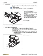
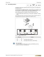
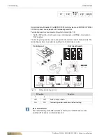
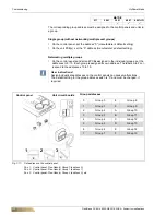
6.12.6 Miniature switch CET.ACEC
User instructions!
If more than two wires must be connected to terminal 13, a supporting terminal must
be provided by others on-site. The supporting terminal must enable connection of
more than two wires.
Besides fan control, units with a cooling function must also be equipped with valve con-
trol.
Units with an installed CET.ACEC and extract-air sensor must have continuous fan
operation. Only one valve control type is allowed.
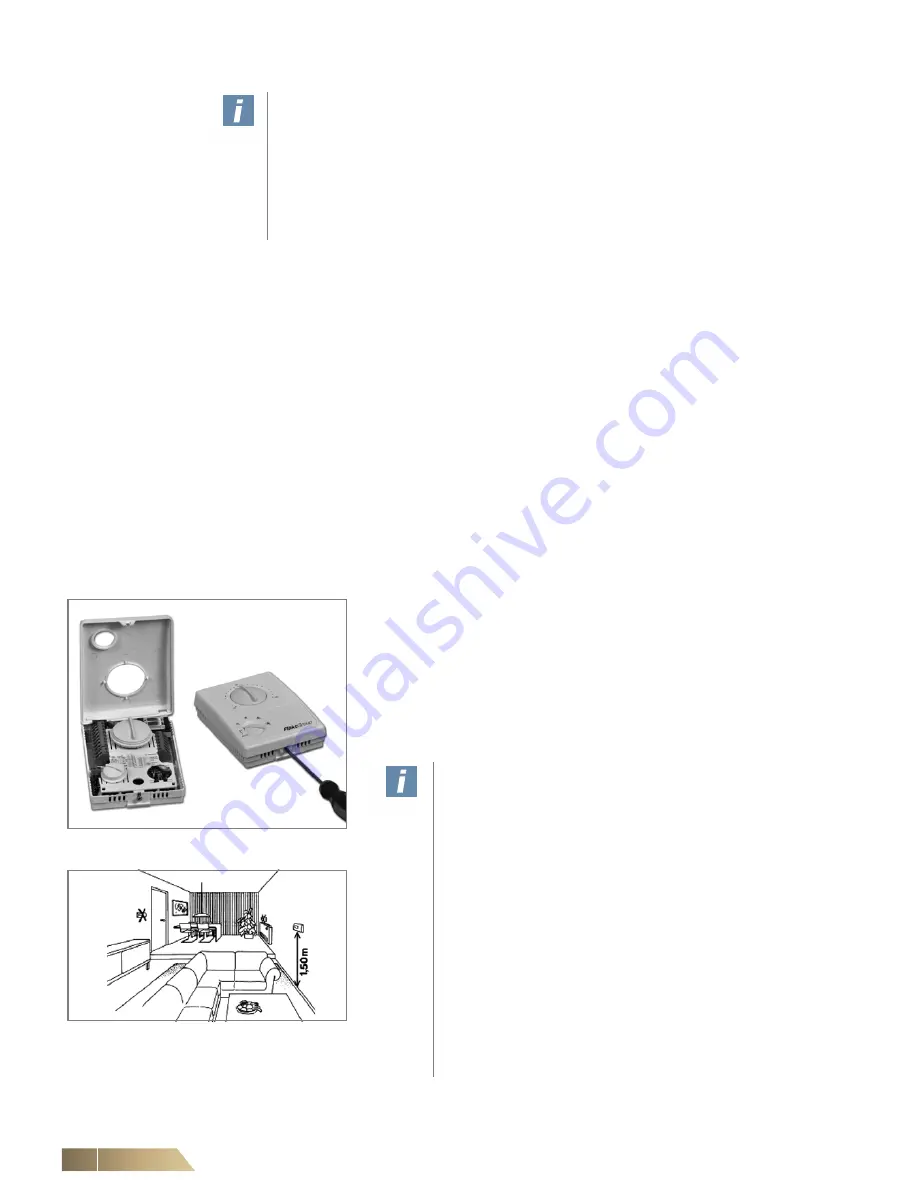
Fig. 6-86: Miniature switch CET. ACEC
Miniature switch:
– Open the miniature switch casing as illustrated.
(see fig. 6-86)
– Fix the casing in a suitable place (see fig. 6-87) using appropriate
screws (max. M4).
– Connect the miniature switch according to the wiring diagram (see
Kapitel 6.11and Kapitel 6.12).
– Close the casing in the reverse order to the opening procedure.
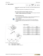
User instructions!
The installation site of the miniature switch is critical for
the precise control
of the room temperature. Therefore do not mount the
miniature switch in the following locations (refer to fig. 6-
87):
– next to doors, windows, passageways etc., since
intense movement of air can cause incorrect mea-
surements.
– on hot or cold walls (e.g. chimney, outside wall), as
wall temperature can cause incorrect measurements
and affect control operation.
– behind blinds and net curtains, as the insulating lay-
ers of air can cause incorrect measurements.
– immediately near unit discharge grilles, since the dis-
charge temperature can cause incorrect measure-
ments.
Fig. 6-87: Installation location