


HyPower-Geko
Maintenance and Troubleshooting
FläktGroup DC-2014-0022-GB 2018-05/R5 • Subject to modifications
121
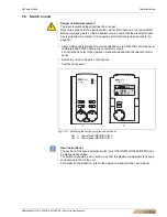
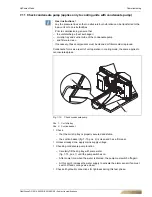
8.3.5 Check the heat exchanger and drip tray for dirt/mold, and clean and disinfect if required.
•
Dismount the drain pan (see fig. 8-5, Pos. 1 and Pos. 2, 2 screws right and left)
and the arrester straps (see fig. 8-5, Pos. 3). Depending on the installation situation
and model, the disassembly of the on-site condensate drain pipe and the sensor of
the condensate pump might be required.
•
Check the heat exchangers (see fig. 8-5, Pos. 4) and the condensate tray for con-
tamination or microbial growth and clean/disinfect these if necessary. Depending
on the installation situation, it might be required to remove the heat exchanger. In
this case, please follow the instructions in Chapter 8.3.7.
Pos. 1:
Condensate tray
Pos. 2:
Fastening
screws (4 parts)
Pos. 3:
Arrester straps
Pos. 4:
Heat exchangers
•
Mount all components in the reverse order
Risk of personal injury!
Injury may be caused by falling parts and sharp edges!
Upon disassembly of the unit, wear helmet, safety shoes and protective gloves. Dis-
assembly should always be performed by two persons
Damage to the unit!
Do not use chemical detergents or disinfecting agents that cause acid or alkaline
reactions and can lead to aluminum or zinc corrosion. Make sure that no remaining
water can discharge from the drain pan!
Fig. 8-5:
Checking heat exchanger and drain pan
Clean drain!
User instructions! Only for units with condensate pump!
Lubricate the drain connection of the condensate tray including the O-ring (see
fig. 8-13, Pos. 7) with lubricant. Set the plastic end piece of the suction hose of the
condensate pump (see fig. 8-6, Pos. 3) on the fittings of the condensate tray outflow
(see fig. 8-6, Pos. 2) until it sits firmly. For for the assembly of the end piece, be sure
that the half-round hole at the edge of the end piece (see fig. 8-6, Pos. 1) is on the
upper side.