


HyPower-Geko
Electrical connection
FläktGroup DC-2014-0022-GB 2018-05/R5 • Subject to modifications
67
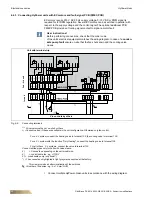
6.7.5 Connecting the inlet sensor (option)
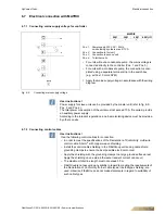
6.7.6 Connecting room sensor/return-air sensor (option)
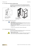
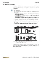
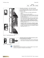
Pos. 1:
Connecting cable (refer to notice on Seite 63)
•
Connect the outdoor sensor according to wiring diagram.
Fig. 6-16: Connecting outdoor sensor
MATRIX
2001
3001
4001
4001+IO
9
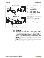
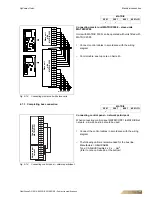
Pos. 1:
Connecting cable (refer to notice on Seite 63)
•
Connect the inlet sensor according to the wiring diagram
(refer to fig. 6-11 on Seite 64). The connecting terminals are
located on the mounting plate of the control panel (refer to
the operation manual for the relevant control panel).
– With 2-pipe change-over units with MATRIX 2000, the con-
nection of an additional room or return-air sensor is only
possible via the AI module.
Fig. 6-17: Connecting inlet sensor
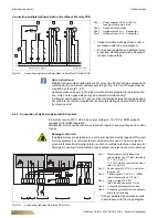
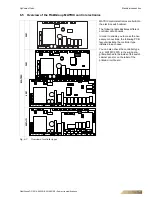
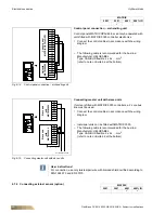
Pos. 1:
Connecting cable (refer to notice on Seite 63)
•
Connect the inlet sensor according to the wiring diagram.
•
Connect the shielding of the sensor line with grounding
clamps to a large ground area!
Fig. 6-18: Connecting inlet sensor
MATRIX
2001
3001
4001
4001+IO
9
9
9
MATRIX
2001
3001
4001
4001+IO
9
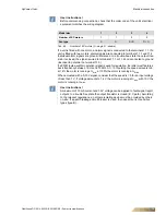
Pos. 1:
Connecting cable (refer to notice on Seite 63)
•
Connect the room or return-air sensor according to the
wiring diagram. The connecting terminals are located on the
mounting plate of the control panel (refer to the operation
manual for the relevant control panel).
•
With 2-pipe change-over units with MATRIX 2000, the
connection of an additional room or return-air sensor is only
possible via the AI module.
Fig. 6-19: Connecting room sensor/return-air sensor