


HyPower-Geko
Hydraulic Connection
FläktGroup DC-2014-0022-GB 2018-05/R5 • Subject to modifications
45
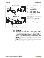
5.3.4 Medium connection in a 4-pipe system
User instructions!
When making a medium connection to the unit, always ensure the correct connec-
tion to the input and output of the heat exchanger! Exchanging the connections can
lead to loss of efficiency! (see fig. 5-9 and fig. 5-10)
The connection fittings of the heat exchanger always have an inner thread. (refer to
Tab. 5-2)
Pos. 1:
Inlet cooling (internal screw thread, see
Tab. 5-2).
Pos. 2:
Return line cooling (internal screw thread, see
Tab. 5-2)
Poz. 3:
Supply line heating (internal screw thread,
see Tab. 5-2)
Pos. 4:
Return line heating (internal screw thread, see
Tab. 5-2)
Fig. 5-9:
Heat exchanger connections 4-pipe system, left connection
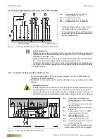
Pos. 1:
Inlet cooling (internal screw thread, see
Tab. 5-2).
Pos. 2:
Return line cooling (internal screw thread, see
Tab. 5-2)
Poz. 3:
Supply line heating (internal screw thread, see
Tab. 5-2)
Pos. 4:
Return line heating (internal screw thread, see
Tab. 5-2)
Fig. 5-10: Heat exchanger connections 4-pipe-system, right connection
Type identification
Connection fittings of the heat exchanger
- internal screw thread
Cooling
Heating
GH11.#WW#.#####
GH12.#WW#.#####
G 1/2"
G 1/2"
G 1/2"
G 1/2"
GH21.#WW#.#####
GH22.#WW#.#####
G 1/2"
G 1/2"
G 1/2"
G 1/2"
GH31.#WW#.#####
GH32.#WW#.#####
G 3/4"
G 3/4"
G 1/2"
G 1/2"
GH41.#WW#.#####
GH42.#WW#.#####
G 3/4"
G 1"
G 1/2"
G 1/2"
Tab. 5-2:
connecting dimensions of the fittings of the heat exchanger, 4-pipe system