


Maintenance and Troubleshooting
HyPower-Geko
124
FläktGroup DC-2014-0022-GB 2018-05/R5 • Subject to modifications
•
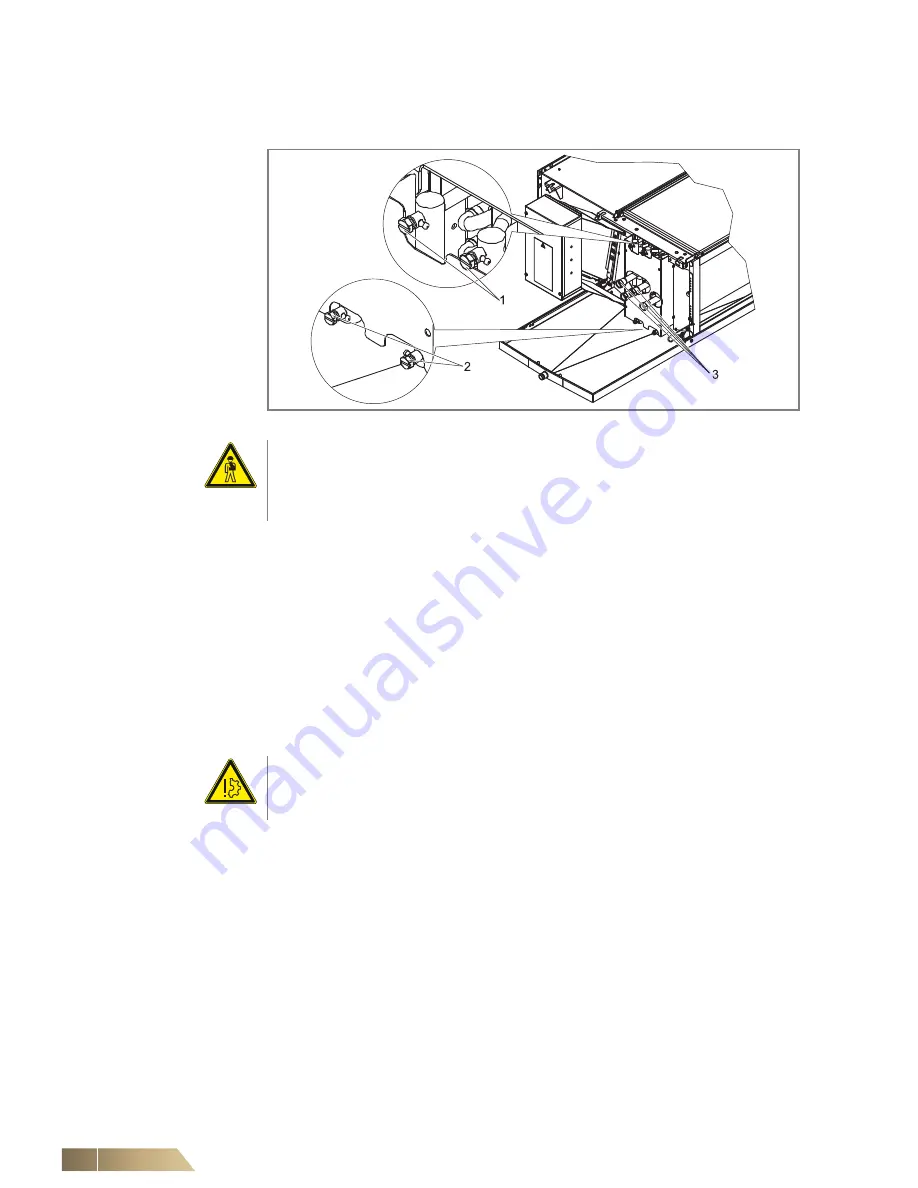
Empty the heat exchanger by opening all venting and draining screws at the heat
exchanger connections (see fig. 8-8, Pos. 1 and Pos. 2) and loosen the screw
connectors of the medium connections at the heat exchanger (see fig. 8-8, Pos. 3).
Pos. 1:
Vent screws
Pos. 2:
Drain screws
Pos. 3:
Heat exchanger
connections
•
Dismount the condensate tray according to the instructions in Chapter 8.3.5.
•
Dismount the heat exchanger. Loosen 2 fixing screws of heat exchanger cover plate on
both sides of the unit by one revolution. (refer to fig. 8-9, Pos. 1). Then remove the
oppositely-arranged fixing screws of the heat exchanger cover plate, remove the cover
plate (see fig. 8-9, Pos. 2). Loosen 2 fixing screws of the adapter plate on both sides of
the unit and remove the plate (refer to fig. 8-9, Pos. 3). On the side of heat exchanger
connections loosen the fixing screws of the bottom angle panel and remove it (see
fig. 8-9, Pos.4). Remove the bottom cross strip (see fig. 8-9, Pos.5). First completely
remove the screws that were loosened by one revolution (see fig. 8-9, Pos.1) and
carefully pull the heat exchanger downwards and remove.
•
Check the heat exchanger for soiling or microbial growth and clean/disinfect it if
necessary by rinsing or vacuuming/blowing out.
Fig. 8-8:
Draining heat exchangers
Risk of personal injury!
Injury may be caused by falling parts and sharp edges!
Upon disassembly of the unit, wear helmet, safety shoes and protective gloves. Dis-
assembly should always be performed by two persons
Damage to the unit!
Do not use a high-pressure washer for cleaning the heat exchanger, since this can
lead to deformations and damage of the aluminum fins!