


HyPower-Geko
Electrical connection
FläktGroup DC-2014-0022-GB 2018-05/R5 • Subject to modifications
59
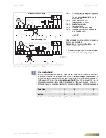
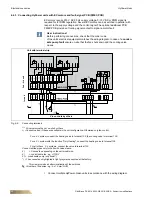
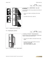
If a unit is fitted with one motor, an alarm signal is conducted to the terminals 11.1. If a
unit is fitted with two motors, alarm signals are conducted to terminals 11.1 and 11.2.
Individual alarm signals are ground-referenced. In a trouble-free state the output tran-
sistor is closed, the signal is wired to terminals 11.1 or 11.2 and connected to ground
(identical to potential on terminal 11.5).
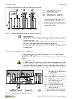
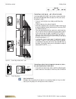
If a PWM (pulse-width modulation) signal is used for regulation, the latter must feature a
basic frequency between 1 KHz and 10 KHz. At < 10% pulsing the speed amounts to 0;
at 14% the motor is running at n
min
; at 100% the motor is running at n
max.
When actuated with a 0-10 V signal, consider that the speed is = 0 for an input voltage
of less than 1 V; if voltage amounts to 1.4 V the motor is running at n
min
; with 10 V the
motor is running at n
max.
User instructions!
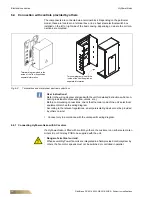
Before commencing connections, check that the order code of the unit's electrical
equipment matches the wiring diagram.
Model size
1
2
3
4
Number of EC motors
1
1
2
2
Fan type
S
D
S + D
D + D
Tab. 6-5:
Number of EC motors (S...single, D...double)
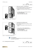
User instructions!
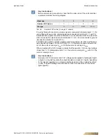
A maximum of 10 mA current and 30 V voltage can be applied to fault-signal report
outputs. In a trouble-free state the output transistor is closed (E, C path). According
to the relevant regulations, an all-pole isolating device must be provided by others
on-site. If an earth leakage circuit breaker is used, then use all-current sensitive
types (type B).