


Electrical connection
HyPower-Geko
56
FläktGroup DC-2014-0022-GB 2018-05/R5 • Subject to modifications
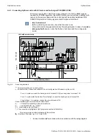
6.4
Connection with controls provided by others
The components are connected via a terminal block. Depending on the particular
model, these are located in a terminal box or in a sheet steel electrical switch box
installed on the left or right side of the basic casing, depending on where the coil con-
nections are mounted.
•
Connect only in accordance with the unit-specific wiring diagram.
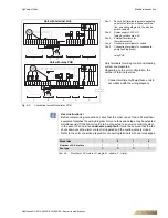
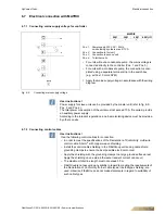
6.4.1 Connecting HyPower-Geko with AC motors
If a HyPower-Geko is fitted with control by others, the customer can either select a ter-
minal strip or FG-relay PCB to be supplied with the unit.
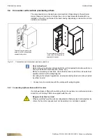
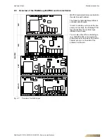
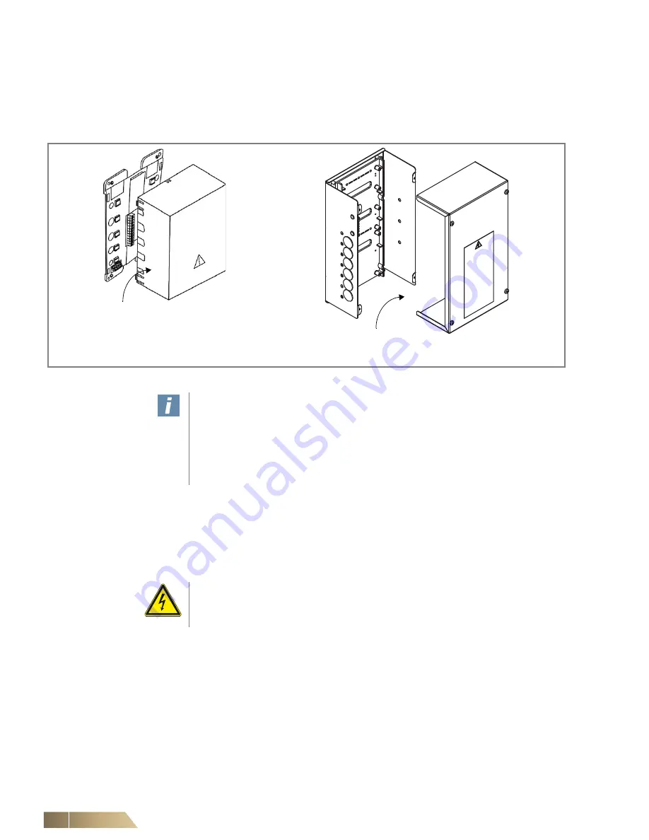
Fig. 6-2:
Terminal box and metal sheet electrical control box
User instructions!
Refer to the wiring diagram enclosed with the unit for detailed instructions when con-
necting individual components (fan, valves, etc.).
Before commencing connections, check that the order code of the unit's electrical
equipment matches the wiring diagram.
According to the relevant regulations, an all-pole isolating device must be provided
by others on-site!
Terminal diagram glued to the
inside of the lid or supplied as
separate information
Terminal diagram glued to the
inside of the lid or supplied as
separate information
Danger of electrical current!
When several HyPower fan coils are integrated in a field-provided control system by
others, the fan motor speeds must not be switched or controlled in parallel.