


Electrical connection
HyPower-Geko
60
FläktGroup DC-2014-0022-GB 2018-05/R5 • Subject to modifications
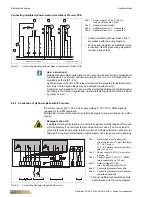
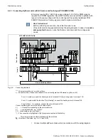
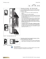
6.4.3 Connecting HyPower units with EC motors and fault-signal PCB (FMEC.PCB)
EC motors require 230 V AC 50 Hz supply voltage. 0-10 V DC or PWM signal is
required for for RPM regulation. Several EC motors can be switched in parallel with
respect to the supply voltage and the control signal.The optional additional PCB
FMEC.PCB provides a floating signal contact to signal a motor fault.
•
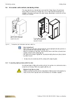
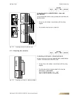
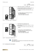
Connect multiple HyPower-Geko units in accordance with the wiring diagram.
User instructions!
Before performing connections, check that the order code
of the unit's electrical equipment matches the wiring diagram. In case of a
conden-
sate pump fault
ensure on-site that the fan shuts down and the cooling valve
closes.
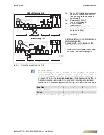
Fig. 6-6:
Connecting terminals
1) =
N-jumpers must be set on-site by others
2) =
Connect valves, if these are available in the unit configuration. Otherwise only fan control.
For a 4-L system, connect the heating valve to terminal 105, the cooling valve to terminal 103.
For a 2-L system with the function "Only Heating", connect the heating valve to terminal 105.
For all others 2-L systems, connect the valve to terminal 103.
Connect dotted pipes only for units with valve sleeve.
3 )
= Second fan depending on the unit model size.
4 )
= control cable fan; e.g. JY(St)Y
5 ) = condensate pump is optional *)
*) =The connections highlighted in light gray were executed at the factory.
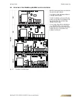
This view provides a better visualization of the switches.
= Number of line wires: e.g: 5 x 1.5 mm² NYM
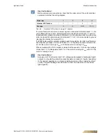
Unit with terminal strip
1s
t un
it
2nd
- 4t
h un
it
Via controls by others