


HyPower-Geko
Electrical connection
FläktGroup DC-2014-0022-GB 2018-05/R5 • Subject to modifications
73
6.8.2 Network structure MATRIX.Net
A network can consist of one or several (up to 16) groups. Global modules can also be
integrated into the network. The network structure/network topology of MATRIX.Net
should be linear – see “Topologies of network MATRIX.Net” on page 73.
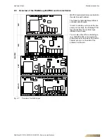
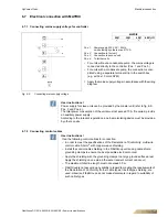
The maximum extent of the MATRIX.Net network is shown in fig. 6-29.
Fig. 6-29: Example of maximum extent of the network
At its maximum extent, the network can consist of:
– A maximum of 16 unit groups – see “Topologies of network MATRIX.Net” on page
73
– Two digital input modules (MATRIX.DI)
– Two analog input modules (MATRIX.AI)
– Two digital output modules (MATRIX.DO)
– Control panels with display MATRIX OP71
– One extract-air manager (MATRIX.EM)
– up to 16 LON modules (MATRIX.LON).
The arrangement of the unit groups and global modules in the network is arbitrary. The
following factors are critical for the assignment of units, control panels and global mod-
ules to a group:
– Setting of the group address switch (refer to the chapter “Commissioning and Test-
ing” in the relevant operation manual)
– Or the assignment of a module input and output to a unit group via the MATRIX.PC
service tool (refer to the online help for the service software).
The physical assignment itself is not decisive.
6.8.3 Topologies of network MATRIX.Net
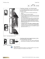
The MATRIX.Net can be set
in a line structure and a line structure with branch
feeder.
All units equipped with MATRIX system can access this data bus.
The data bus must be terminated at both physical ends to avoid reflections which can
interfere with data transfer. Switchable bus terminating resistors are integrated on the
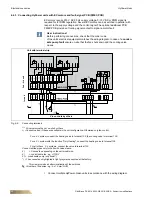
respective boards enabling safe termination – refer to Chapter "Connecting
MATRIX.Net".
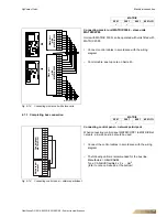
Group 2
Group 3
Group 1
Group 4
Group 16