4-56
I
NSTALLING
ALINTE
4
PAGE
E
QUIPMENT
AND
S
OFTWARE
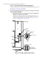
4.6.5.2 Heights (Inca) Earth Cable Fitting
From the engine end:
1.
Switch off the engine and isolate from mains supply.
2.
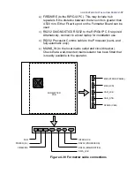
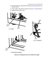
Obtain the V6_Processor_Earth (99700651) from the support pack
and pass one end through the cable entry slot (see
Figure 4.41 on
page 4-56
(a).
3.
Fit one end of the cable to the base earth stud.
From the processor end:
4.
Route the cable to the processor earth stud shown in
Figure 4.41 on
page 4-56
(c).
4.6.6 Fitting the PC G10 Film Filter
If the RIP PC is located close to a manual or semi-automatic engine,
then there is a risk that the monitor light can cause plate fogging.
Assess the risk with the customer and fit the supplied encapsulite
G10 yellow film as follows:
1.
Cut out the film sheet so that it fits the monitor screen.
2.
Tape the film to the monitor from all four sides.
4.6.7 Final Visual Checks
As a final check make sure that:
All the module interface cables are connected.
All the cables to ancillary equipment are connected.
All transit fixings are accounted for.
The correct circuit breaker (type and rating) is fitted for the
platesetter room mains distribution to the machine (see the ratings
label at the rear of the Engine).
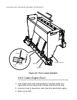
4.6.7.1 Plate Output Alignment Checks
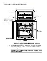
To make sure plates are not skewed and jammed at the output mod-
ule as a result of engine transit, carry out the following checks:
Summary of Contents for alinte4page
Page 1: ......
Page 12: ...PRELIMINARIES...
Page 29: ...ALINTE4PAGE INSTALLATION GUIDE 2 7 Figure 2 5 Autofeeder elevator warning label...
Page 40: ...2 18 SAFETY ON THE ALINTE4PAGE Figure 2 13 Location of interlock covers alinte4page SAL 2 1...
Page 48: ...2 26 SAFETY ON THE ALINTE4PAGE...
Page 56: ...3 8 UNPACKING AND HANDLING...
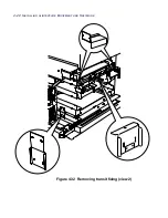
Page 98: ...4 42 INSTALLING ALINTE4PAGE EQUIPMENT AND SOFTWARE Figure 4 32 Removing transit fixing view 2...

