ALINTE
4
PAGE
I
NSTALLATION
G
UIDE
5-15
4.
Calculate the average of all three values recorded so far. The
resulting average is the focus setting for 48 resolution for all plate
thicknesses.
5.
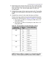
Enter the resulting resolution value into the 48, 50 and 1200 BCF
positions in the Final Values Table for all plate thicknesses. For the
low resolutions, the focus does not depend on plate thickness as the
depth of focus is higher than for the high resolutions.
6.
Save and exit the Final Values Table and Optics>mmi.
7.
Save NVRAM if any changes have been made.
8.
Run linearisation to verify that the dots% are correct.
NOTE: If any of the focus conditions cannot be met, try a differ-
ent value for ND and check the processor setup. Finish the
required setups as well as possible and check the resulting
quality using an S&T page. If the results are still unsatisfactory
and cannot be improved, consult FFEI Customer Services.
5.3.4 Calibrate for Laser Exposure
5.3.4.1 MMI Menus
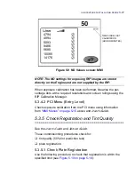
Exposure calibration sets up a constant exposure power level at the
drum surface for all resolutions. The required exposure level is
entered from the MMI. A recommended value is
50
which can be
edited but
only after advice from the plate supplier
. This value cor-
responds to
65
μ
J/cm
2
for 1200, 48, 50res and
90
μ
J/cm
2
for 2400,
96, 100, 3600 and 144res.
1.
From the MMI console (if fitted), display the TOOLS menu and press
Exposure Calibration
(lower righthand side button) to obtain the
Exposure Calibration screen:
Summary of Contents for alinte4page
Page 1: ......
Page 12: ...PRELIMINARIES...
Page 29: ...ALINTE4PAGE INSTALLATION GUIDE 2 7 Figure 2 5 Autofeeder elevator warning label...
Page 40: ...2 18 SAFETY ON THE ALINTE4PAGE Figure 2 13 Location of interlock covers alinte4page SAL 2 1...
Page 48: ...2 26 SAFETY ON THE ALINTE4PAGE...
Page 56: ...3 8 UNPACKING AND HANDLING...
Page 98: ...4 42 INSTALLING ALINTE4PAGE EQUIPMENT AND SOFTWARE Figure 4 32 Removing transit fixing view 2...


