


ALINTE
4
PAGE
I
NSTALLATION
G
UIDE
5-29
3.
Skew error differences between the measurements
A
and
B
should
be less than
100
microns for each plate.
4.
Possible skew errors could be caused by poor pull bar alignment -
see the alignment procedure in the
Service Guide
.
5.5.4 Check Image Base Position in RIP
Check that you can move the image base relative to the lead edge
from the
Start Y
option on the RIP Job Ticket (Output) panel.
Set the position at
0
and the Y position corresponds to
2 mm
from the
leading top edge of the plate. To move the image away from the crop
marks in the Y direction, add a small amount.
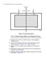
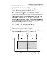
5.5.5 Check for Image Centering
1.
Check that the image is centered on the plate.
2.
Make sure the image is centered at equal distance (
A
and
B
) from the
outer crop marks shown in
Figure 5.18 on page 5-29
.
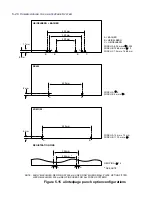
Figure 5.18 Centering the image (with punch)
PLATE
A
B
IMAGE
PUNCH
CENTRE
Summary of Contents for alinte4page
Page 1: ......
Page 12: ...PRELIMINARIES...
Page 29: ...ALINTE4PAGE INSTALLATION GUIDE 2 7 Figure 2 5 Autofeeder elevator warning label...
Page 40: ...2 18 SAFETY ON THE ALINTE4PAGE Figure 2 13 Location of interlock covers alinte4page SAL 2 1...
Page 48: ...2 26 SAFETY ON THE ALINTE4PAGE...
Page 56: ...3 8 UNPACKING AND HANDLING...
Page 98: ...4 42 INSTALLING ALINTE4PAGE EQUIPMENT AND SOFTWARE Figure 4 32 Removing transit fixing view 2...