ALINTE
4
PAGE
I
NSTALLATION
G
UIDE
4-3
E
)
Repeat steps
B
)
and
C
)
for the other two directions.
F
)
Total the readings for each direction separately.
G
)
If the gradient total is less than
30
mm (
1.18
in) for all three
directions then proceed with the installation.
Figure 4.1 Checking floor gradients: alinte4page
4.
If the platesetter floor level is uneven then check for a more suitable
area nearby.
5.
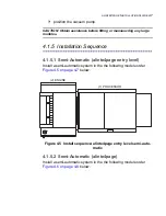
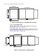
If the floor level gradient is within specification, then start the
installation using the recommended sequence. This sequence is
based on a very precise engine horizontal (traverse) travel level
difference of less than
0.5 mm
between the two ends.
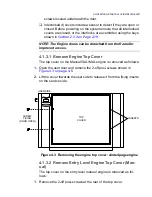
4.1.3 Remove the Module Covers
See
Figure 4.2 on page 4-4
. and
Figure 4.3 on page 4-5
.
(X1)
(X2)
(Y)
FLOOR GRADIENT RISE/FALL REQUIREMENT:
(X1) AND (X2) = LESS THAN 30 mm
(Y) = LESS THAN 30 mm
Summary of Contents for alinte4page
Page 1: ......
Page 12: ...PRELIMINARIES...
Page 29: ...ALINTE4PAGE INSTALLATION GUIDE 2 7 Figure 2 5 Autofeeder elevator warning label...
Page 40: ...2 18 SAFETY ON THE ALINTE4PAGE Figure 2 13 Location of interlock covers alinte4page SAL 2 1...
Page 48: ...2 26 SAFETY ON THE ALINTE4PAGE...
Page 56: ...3 8 UNPACKING AND HANDLING...
Page 98: ...4 42 INSTALLING ALINTE4PAGE EQUIPMENT AND SOFTWARE Figure 4 32 Removing transit fixing view 2...


