2 CANopen
Festo – EMCA-EC-C-HP-EN – 2017-11e – English
25
2.2.4
CAN bus cabling
The CAN bus offers a simple, interference-resistant method of networking all the components of a sys
tem together. A requirement for this is that all of the subsequent instructions on cabling are observed.
120
Ω
120
Ω
CAN shield
CAN-GND
CAN-L
CAN-H
CAN shield
CAN-GND
CAN-L
CAN-H
CAN shield
CAN-GND
CAN-L
CAN-H
Bus length
End participant
End participant
Participant
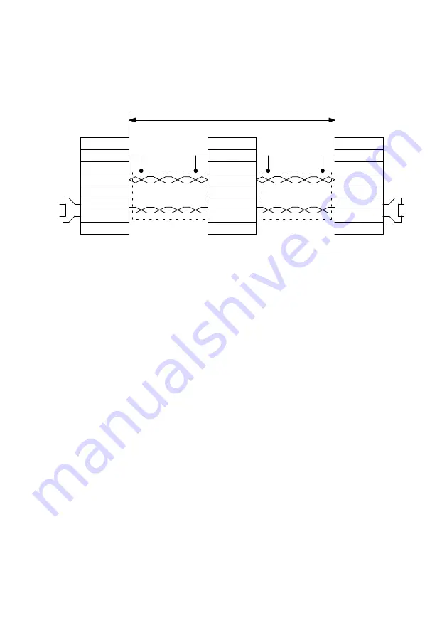
Fig. 2.3
Cabling example
–
The individual nodes of the CAN bus network are connected in series. The CAN bus signals are
passed from component to component through the CAN bus cable
è
–
Both end participants of the CAN bus network must be terminated with a terminating resist
or (120 Ω, ±5 %). Observe the information and notes on this in the corresponding documentation of
the end participants.
–
Screened cable with 2 twisted conductor pairs must be used for the CAN bus wiring
è
Tab. 2.5. The
first twisted conductor pair is used for the CAN signals CAN-H and CAN-L. The second twisted con
ductor pair is used for the load CAN-GND (reference potential for CAN signals). The screening of the
CAN bus cable must be connected to the CAN shield port at each node.
–
The use of adapters is not recommended for CAN bus cabling. If despite this an adapter is used, a
plug connector with metal housing is recommended. For plug connectors with a plastic or metal
housing, ensure that the screening of the CAN bus cable is connected properly.
–
To keep the disturbance coupling as low as possible, CAN bus cables should not be laid parallel to
supply cables (e.g. motor cables). In addition, supply cables with screening must be earthed cor
rectly.
–
To construct an interference-free CAN bus cabling, observe the information and notes in the Control
ler Area Network protocol specification, version 2.0, issue 1991, of Robert Bosch GmbH.
Summary of Contents for EMCA-EC-67 CO Series
Page 33: ...2 CANopen Festo EMCA EC C HP EN 2017 11e English 33 ...
Page 73: ...3 EtherCAT with FHPP Festo EMCA EC C HP EN 2017 11e English 73 ...
Page 87: ...4 EtherNet IP with FHPP Festo EMCA EC C HP EN 2017 11e English 87 ...
Page 113: ...6 PROFINET IO with FHPP Festo EMCA EC C HP EN 2017 11e English 113 ...
Page 116: ...7 FHPP 116 Festo EMCA EC C HP EN 2017 11e English ...
Page 140: ...8 FHPP standard data I O data 140 Festo EMCA EC C HP EN 2017 11e English ...
Page 148: ...9 Measuring reference system 148 Festo EMCA EC C HP EN 2017 11e English ...
Page 210: ...10 Control via FHPP 210 Festo EMCA EC C HP EN 2017 11e English ...
Page 223: ...11 Monitoring of the drive behaviour Festo EMCA EC C HP EN 2017 11e English 223 ...
Page 367: ...D CANopen communication Festo EMCA EC C HP EN 2017 11e English 367 ...
Page 402: ...F Diagnostics and fault clearance 402 Festo EMCA EC C HP EN 2017 11e English ...
Page 413: ...EMCA EC 67 CO DIO EC EP PN Festo EMCA EC C HP EN 2017 11e English 413 ...
Page 414: ...EMCA EC 67 CO DIO EC EP PN 414 Festo EMCA EC C HP EN 2017 11e English ...
Page 415: ......


