background image

6.7 

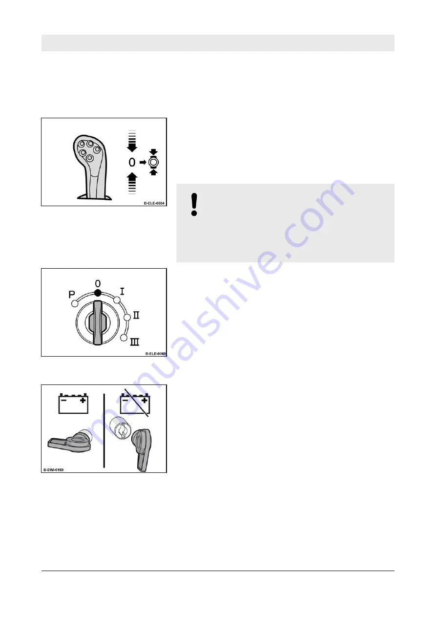
Park the machine in secured condition.

1.

Drive the machine onto level and firm

ground.

2.

To stop the machine return the travel lever

to middle position and shift it to the right to

lock (parking brake position).

ð

The parking brake warning lamp lights

up.

NOTICE!
Danger of engine damage!

– Do not shut down the engine all

of a sudden from full load speed,

but let it idle for about 2 minutes.

3.

Turn the ignition key to position “0” and pull

it out.

4.

Open and secure the engine hood

Ä

 Chapter 8.2.1 „Open and secure the

engine hood“ on page 136

.

5.

Turn the main battery switch counter-clock-

wise and pull it out.

6.

Close the engine hood and lock it if neces-

sary.

Fig.  78

Fig.  79

Fig.  80

Operation – Park the machine in secured condition.


BW 213 D-5


115

Summary of Contents for BOMAG BW 213 D-5

Page 1: ...BW 213 D 5 Single drum roller Operating Instruction Maintenance Instruction Original Operating Instructions S N 101 586 48 1001 08 2016 008 202 10 EN...

Page 2: ...2...

Page 3: ...damentals for safe operation 29 3 3 1 Remaining dangers remaining risks 29 3 3 2 Regular safety inspections 29 3 3 3 Modifications and alterations to the machine 29 3 3 4 Damage defects misuse of safe...

Page 4: ...hine 49 3 8 Refuelling 51 3 9 What to do in events of emergency 52 3 9 1 Actuating the emergency stop switch 52 3 9 2 Disconnect the battery 52 3 9 3 Towing the machine 52 3 10 Maintenance work 54 3 1...

Page 5: ...he fuel level 88 5 4 2 Refuelling 88 5 5 Checking the hydraulic oil level 90 5 6 Checking the coolant level 91 5 7 Checking wheels and tyres 93 6 Operation 95 6 1 Setting up the work place 96 6 1 1 Ad...

Page 6: ...ort 126 7 2 Loading the machine 127 7 3 Lashing the machine to the transport vehicle 129 7 4 Loading by crane 130 7 5 After transport 132 8 Maintenance 133 8 1 Preliminary remarks and safety notes 134...

Page 7: ...ion of the coolant 170 8 8 4 Renewing the AdBlue DEF filter 171 8 8 5 Check the hydraulic lines 172 8 8 6 Servicing the battery checking the main battery isolation 174 8 8 7 Servicing the air conditio...

Page 8: ...ng the printer ribbon in the printer 202 8 11 8 Drain the fuel tank sludge 203 8 11 9 Measures prior to extended shutdown period 203 9 Trouble shooting 207 9 1 Preliminary remarks 208 9 2 Starting the...

Page 9: ...1 Introduction Introduction BW 213 D 5 9...

Page 10: ...iving permit must be acquired from the responsible authori ties The machine is equipped with latest tech nology Now it s a matter of handling your machine properly and keeping it in good working order...

Page 11: ...ired for this purpose is by all means lower than the faults that may occur in case of non compliance The machine must only be serviced by quali fied and authorized personnel A description of all neces...

Page 12: ...constitute an extension of the warranty and liability conditions specified in the general sales and delivery conditions of BOMAG GmbH We wish you successful work with your BOMAG machine Introduction...

Page 13: ...e plate Please enter here Machine type 1 Serial number 2 Please enter here Engine type 1 Engine number 2 Fig 1 Machine type plate example Fig 2 Engine type plate example Introduction Machine type plat...

Page 14: ...Introduction Machine type plate and engine type plate BW 213 D 5 14...

Page 15: ...2 Technical data Technical data BW 213 D 5 15...

Page 16: ...84 Dimensions in millimetres Dimensions in inch Weights Max operating weight 14800 32628 kg lbs Operating weight with ROPS cabin CECE 12510 27580 kg lbs Axle load drum CECE 7500 16535 kg lbs Axle load...

Page 17: ...mph Max gradability without with vibration soil dependent 45 43 Drive Engine manufacturer Deutz Type TCD 3 6 L4 Cooling Fluid Number of cylinders 4 Rated power ISO 3046 90 kW Rated power SAE J 1995 12...

Page 18: ...ng angle 35 Oscillation angle 12 Inner track radius 3680 145 mm in Exciter system Drive system hydrostatic Frequency 1 2 30 34 1800 2040 Hz vpm Amplitude 1 2 2 10 1 10 0 083 0 043 mm in Centrifugal fo...

Page 19: ...hese values may vary because of the prevailing operating conditions 2 1 1 Noise data LpA 77 dB A determined acc to ISO 11204 and EN 500 LWA 108 dB A determined acc to ISO 3744 and EN 500 2 1 2 Vibrati...

Page 20: ...Technical data Noise and vibration data BW 213 D 5 20...

Page 21: ...3 Concerning your safety Concerning your safety BW 213 D 5 21...

Page 22: ...ad and comply with these safety regula tions If necessary the customer must obtain the relevant signatures as confirmation Furthermore the following obviously also applies n applicable accident preven...

Page 23: ...ns marked accordingly indi cate a dangerous situation that could lead to fatal or severe injuries if this warning is disregarded CAUTION Danger of injury if failing to comply Sections marked according...

Page 24: ...e equip ment is required to be provided by the operating company Working clothes Tight fitting working clothes with low tear resistance tight sleeves and without any projecting parts protects against...

Page 25: ...construction and road bases n Compaction of bituminous material e g road surface layers Intended use also includes compliance with the specified operating maintenance and repair measures 3 1 5 Imprope...

Page 26: ...too small contact area danger of tipping over n Using the machine for towing n use to pull down walls or demolish buildings transporting persons except the machine driver is prohibited starting and o...

Page 27: ...ut any remaining dangers The operating company must determine whether there are special operation hazards such as a toxic atmosphere or limiting soil con ditions Such conditions requires special addi...

Page 28: ...pany aged 18 or more Observe your local laws and regulations Rights obligations and rules of conduct for driver or operator The driver or operator must n be instructed about his rights and obliga tion...

Page 29: ...he actual danger zone of the machine Persons remaining in this area must pay partic ular attention to the machine so that they can react immediately in case of a possible mal function an incident or f...

Page 30: ...nor must they be made ineffective 3 3 5 Roll Over Protective Structure ROPS On machines with cab the ROPS is an integral part of the cab The frame of the machine must not be warped bent or cracked in...

Page 31: ...A defect ROPS must generally be replaced with an original spare part in close coordination with the manufacturer Concerning your safety Fundamentals for safe operation BW 213 D 5 31...

Page 32: ...ame of substance n Possible dangers n Composition information on constituents n First Aid measures n Fire fighting measures n Measures in case of accidental release n Handling and storage n Limitation...

Page 33: ...d Wear your personal protective equipment protective gloves protective clothing CAUTION Health hazard caused by contact with diesel fuel Wear your personal protective equipment protective gloves prote...

Page 34: ...us substance Always keep diesel fuel in proper containers Immediately bind spilled diesel fuel with an oil binding agent Dispose of diesel fuel and fuel fil ters according to regulations Concerning yo...

Page 35: ...tective clothing CAUTION Health hazard caused by contact with oil Wear your personal protective equipment protective gloves protective clothing Do not inhale any oil vapours Avoid contact CAUTION Dang...

Page 36: ...Immediately bind spilled oil with an oil binding agent Dispose of oil and oil filter according to regulations Concerning your safety Handling fuels and lubricants BW 213 D 5 36...

Page 37: ...nal protective equipment protective gloves protective clothing goggles Should pressure fluid penetrate the skin immediate medical help is required WARNING Danger of burning by ignited hydraulic oil Do...

Page 38: ...tact CAUTION Danger of slipping on spilled oil Immediately bind spilled oil with an oil binding agent ENVIRONMENT Oil is an environmentally haz ardous substance Always keep oil in proper con tainers I...

Page 39: ...sed by contact with coolant and coolant addi tives Wear your personal protective equipment protective gloves protective clothing Do not inhale any fumes Avoid contact CAUTION Danger of slipping on spi...

Page 40: ...tely bind spilled coolant with an oil binding agent and dis pose of it according to regula tions Dispose of coolant according to regulations Concerning your safety Handling fuels and lubricants BW 213...

Page 41: ...n or eyes immediately with lots of clear water Immediately call for medical advice in case of cauterization WARNING Danger of injury caused by exploding gas mixture Remove the plugs before starting to...

Page 42: ...ENVIRONMENT Battery acid is an environmen tally hazardous substance Dispose of battery and battery acid according to regulations Concerning your safety Handling fuels and lubricants BW 213 D 5 42...

Page 43: ...nts Always use appropriate lifting and lashing means on the lifting and lashing points Use lifting and lashing gear only in the pre scribed direction of load application Lifting tackle must not be dam...

Page 44: ...After the transport loosen the articulation lock again as otherwise the machine wouild not be steerable Concerning your safety Load transport the machine BW 213 D 5 44...

Page 45: ...are beside or under the machine n the machine is free of oily and combustible materials n all access steps grips and platforms are free of obstacles grease oils fuel dirt snow and ice n all safety el...

Page 46: ...ments Do not inhale exhaust fumes because they contain toxic substances which could cause damage to health unconsciousness or even death For operation in closed or partly closed rooms ensure adequate...

Page 47: ...ways wear the seat belt when driving Do not drive on bases with insufficient load bearing capacity Do not drive on ice and snow If the machine has contacted high voltage power lines n do not leave the...

Page 48: ...k with vibration on hard concrete cured bitumen layers or extremely frozen ground Always keep a sufficient distance when passing through subways under bridges tun nels electric power lines etc 3 7 3 D...

Page 49: ...e high risk of tip ping over and the related risk of severe or even fatal accidents 3 7 5 Working with vibration When compacting with vibration you must always check the effect of the vibration on nea...

Page 50: ...ntended use Do not jump off the machine but use hand grips and access steps Mark machines which could be in the way with a clearly visible sign When parking on ascents or descents use appropriate mean...

Page 51: ...arging than diesel fuel with a higher sulphur content You should therefore always make sure that the filling system is properly grounded and that there is equipotential bonding to the machine If neces...

Page 52: ...the emergency stop as a service brake 3 9 2 Disconnect the battery In events of emergency e g in case of a cable fire disconnect the battery from the vehicle network Pull out the main battery switch o...

Page 53: ...re able to withstand the load and are fastened at the points pro vided for this purpose Before removing the towing facility apply appropriate measures to secure the machine against unintended rolling...

Page 54: ...s and platforms are free of obstacles grease oils fuel dirt snow and ice Use only the intended access steps and grips to mount the machine For overhead maintenance work use the access steps and workin...

Page 55: ...eck all con nections and fittings for leaks Hydraulic hoses must be visually inspected at regular intervals Do not mix up hoses by mistake Only genuine BOMAG replacement hydraulic hoses ensure that th...

Page 56: ...s cold Catch coolant and dispose of it environmentally 3 10 4 Maintenance work on electric components and battery Before starting to work on electric parts of the machine disconnect the battery and co...

Page 57: ...e right tools at hand If neces sary have the tyres assembled in a qualified workshop Always ensure the correct tyre pressure and do not exceed the specified maximum pressure When checking the tyre pre...

Page 58: ...not direct the wter jet to electrical insulation material or cover it beforehand Do not guide the water jet into the exhaust pipe and into the air filter 3 10 8 After maintenance work Reassemble all g...

Page 59: ...ning sign Only operate the machine after it has been repaired Repairs must only be performed by an expert qualified person When replacing safety relevant components only original spare parts must be u...

Page 60: ...Warning sticker Danger of crushing 2 Information sticker Lifting point 3 Information sticker Lashing point 4 Information sticker Engine oil drain 5 Information sticker Coolant drain 6 Information stic...

Page 61: ...cker Diesel 2 Information sticker Main battery switch plus side 3 Warning sticker Vehicle voltage 12 V 4 Operation sticker Main battery switch 5 Information sticker Hydraulic oil Concerning your safet...

Page 62: ...Instruction sticker Always wear your seat belt Fig 12 Concerning your safety Signage BW 213 D 5 62...

Page 63: ...4 Display and control elements Display and control elements BW 213 D 5 63...

Page 64: ...and warning lamps 2 INFO 3 display field 3 INFO 2 display field 4 INFO 1 display field 5 Engine rpm meter 6 not used 7 Fuel level gauge 8 not used 9 Button Reduce frequency 10 Button Increase frequen...

Page 65: ...d clean the radiator If neces sary repair the engine Coolant level warning lamp Lights up if the coolant level is too low The engine is shut down after a short while Check coolant level check cooling...

Page 66: ...river s seat warning lamp Lights up when the driver s seat is not occu pied If the machine is travelling the warning buzzer will sound and the machine is deceler ated after 3 seconds To continue drivi...

Page 67: ...e engine has started the vibration frequency is always at maximum value The display appears only after pressing one of the two buttons and disappears again after a time Designation Note Immobilizer co...

Page 68: ...ts optional equipment 4 Rotary switch for engine speed 5 Rotary switch for direction indicators optional equipment 6 Rotary switch for hazard light system optional equipment 7 Rotary switch for lighti...

Page 69: ...n switch off unlock Turn the Emergency Stop switch clockwise and let it go NOTICE In case of frequent use the wear on the multi discs brakes will be very high Do not use the emergency stop switch as s...

Page 70: ...de The engine speed automati cally adapts to the power requirements This enables economical operation Position Right Full load position MAX 4 1 2 5 Rotary switch for direction indicators Position Midd...

Page 71: ...ional equipment 4 1 2 8 Rotary switch for travel ranges Position ramp Travel range to drive on to a transport vehicle Position turtle Working speed range on level ground Position for ward uphill Trave...

Page 72: ...pressure the engine starts Turn the ignition key back to position I when the engine starts The starter switch is designed with a re start lock The ignition key must first be turned back to position 0...

Page 73: ...g horn 2 not used 3 Vibration Vibration on off 4 not used 5 not used 6 Function key F1 Switch over the INFO 1 display field 7 Function key F2 Switch over the INFO 2 display field Display and control e...

Page 74: ...urement active d Push button to stop measure ment only for Terrameter with printer LED lights EVIB value has not increased by more than 10 since the last pass e Push button to print measure ment repor...

Page 75: ...rking lights m Push button for inside cabin light n Push button for front working lights o Push button for flashing beacon p Push button for front windscreen washer q Push button for front windscreen...

Page 76: ...r off Position 1 to 3 Fan stages of different strengths 4 2 2 4 Rotary switch for air conditioning system Position Top Air conditioning on Position Bottom Air conditioning off Optional equipment The a...

Page 77: ...4 2 3 12 V DIN socket Permanent current loadable up to 20 A Fig 34 Display and control elements Cabin BW 213 D 5 77...

Page 78: ...r menu selec tion Press briefly approx 0 5 s to change to the DISPLAY MENU Press long approx 2 s to change to the MAIN MENU 4 Push button arrow up and push button arrow down Change the selection in a...

Page 79: ...occasionally with a cloth or a brush 4 2 5 Fire extinguisher Optional equipment NOTICE Components may get damaged When retrofitting a fire extin guisher install it only in this posi tion Fig 36 Displa...

Page 80: ...pulled off Isolates the batteries from the on board electrics in case of cable fire and fire in the engine compartment as well as protection against unauthorized use NOTICE Danger of damage to the ele...

Page 81: ...4 1 Reversing camera With the monitor connected it enables the driver to check the working range behind the machine without direct vision Optional equipment Fig 38 Display and control elements Outside...

Page 82: ...Display and control elements Outside of machine BW 213 D 5 82...

Page 83: ...5 Tests before taking into operation Tests before taking into operation BW 213 D 5 83...

Page 84: ...s and environ mental protection regulations when handling fuels and lubri cants must be followed Chapter 3 4 Handling fuels and lubricants on page 32 WARNING Danger of injury caused by rotating parts...

Page 85: ...and secure the engine hood Chapter 8 2 1 Open and secure the engine hood on page 136 Close the engine hood again after work is com pleted Tests before taking into operation Notes on safety BW 213 D 5...

Page 86: ...amage and leakage 4 Check bolted connections for tight fit 5 Check engine and exhaust system for leaks 6 Check the belt drive for damage 7 Check machine for contamination and damage 8 Check function o...

Page 87: ...on page 139 Protective equip ment n Working clothes n Protective gloves 1 Pull the dipstick out wipe it off with a lint free clean cloth and reinsert it until it bot toms 2 Pull the dipstick out again...

Page 88: ...amage Never run the fuel tank dry as otherwise the fuel system needs to be bled Monitor the entire refuelling process Contaminated fuel can cause malfunction or even damage of the engine If necessary...

Page 89: ...orking clothes n Protective gloves 1 Clean the area around the filler opening 2 Unscrew the cap and fill in fuel 3 Close the cap Fig 41 Tests before taking into operation Checking the fuel level toppi...

Page 90: ...ed with Panolin HLP Synth 46 always use the same oil to top up With other ester based oils consult the lubrication oil service of the respective oil manufacturer Protective equip ment n Working clothe...

Page 91: ...warning light informs about a coolant level which is too low Protective equip ment n Working clothes n Protective gloves n Safety goggles 1 Check the coolant level in the compensa tion tank WARNING D...

Page 92: ...3 Unscrew the cap and fill in coolant up to the MAX mark 4 Close the cap Tests before taking into operation Checking the coolant level BW 213 D 5 92...

Page 93: ...ngth of min 6 meters Never exceed the permitted max imum pressure The tire pressure can be adapted to the operating conditions within the specified limits A reduced tire pressure improves the traction...

Page 94: ...on page 115 3 Check the tyres for cuts bulges damaged rims missing wheel studs or nuts 4 Have damaged wheels or tyres replaced immediately 5 Unscrew the valve caps and check the front and rear tire pr...

Page 95: ...6 Operation Operation BW 213 D 5 95...

Page 96: ...a and push the seat for ward or back 3 To adapt to the weight of the operator read the weight indication in the window c and if necessary turn lever b until the correct driver s weight has been adjust...

Page 97: ...at to the desired position Optional equipment 6 1 3 Adjust the steering wheel 1 To adjust the inclination kick the pedal down move the steering wheel to the desired position and release the pedal Opti...

Page 98: ...mmobilizer armed the light emitting diode a flashes slowly 1 Slowly enter the six digit user code When entering the code the light emit ting diode 6 lights up with every digit 2 Press the diamond butt...

Page 99: ...ke closed 1 Turn the rotary switch for engine speed to position Middle ECO mode 2 Turn the ignition key to position I All control and warning lights in the instrument cluster light up for a moment 3 I...

Page 100: ...onds without inter ruption and pause for a minute between starting attempts If the engine has not started after two attempts determine the cause 4 Turn the ignition key through position II to position...

Page 101: ...Soil conditions and weather influences impair the gradability of the machine Wet and loose soils considerably reduce ground adhesion of the machine on gradients and slopes Higher risk of accident Whe...

Page 102: ...chine will travel 5 Set the travel lever to Middle position to stop the machine The machine decelerates to a standstill 6 Always apply the parking brake to stop on inclinations or slopes 6 4 3 Applyin...

Page 103: ...the machine will accelerate again to its previous speed If the travel lever is shifted out of neutral posi tion to any travel direction after the machine has stopped and the seat is not occupied the m...

Page 104: ...und supply lines gas water sewage elec tric power If necessary stop compacting with vibration NOTICE Components may get damaged Do not activate the vibration on hard frozen concrete ground Vibration a...

Page 105: ...to the desired position 2 Preselect the desired amplitude with the rotary switch for amplitude pre selection 3 Shift the travel lever slowly to the desired travel direction 4 Actuate the vibration but...

Page 106: ...ess the push button once again to switch off vibration Vibration is switched off 7 After the end of work turn the rotary switch for amplitude pre selection back to position 0 Changing the frequency Fi...

Page 107: ...be detected during compaction work and unnecessary passes avoided Optional equipment 1 Press push button INFO 2 on the travel lever to select the display for the EVIB value When working with vibratio...

Page 108: ...of all passes a higher EVIB value would be dis played Measuring values must only be compared for passes performed in the same direction Since the transducer unit is mounted on the left hand side of th...

Page 109: ...e track to be compacted 2 Select display of EVib values When working with vibration the actual EVIB value will now be displayed Measuring pass with Ter rameter Fig 67 Fig 68 Operation Terrameter BW 21...

Page 110: ...ust have been reached and a valid EVIB value should be displayed 5 When reaching mark 1 press push button Start measurement to start the measuring pass The LED will flash during the measuring pass 6 W...

Page 111: ...oes not increase more than 10 in compar ison to the previous pass 10 Change to the next track and repeat this whole process of recording measuring values 11 Press the Stop measurement button to end a...

Page 112: ...on to delete all saved data 6 6 3 Line graph EVIB Fig 77 Pos Designation Note 1 Pass Total number of measured passes on this track 2 Travel direction 3 Software status of the measuring equipment Fig 7...

Page 113: ...e vious pass in the same travel direction 12 Medium frequency 13 Mean travel speed 14 Track length 15 Raster division in longitudinal direction Division of the measuring track track length into fixed...

Page 114: ...e location of a fault excessive or insufficient compaction 20 Identification of jump operation thin line Indicates jumping of the drum on the marked track section thin line The bar diagram differs fro...

Page 115: ...of engine damage Do not shut down the engine all of a sudden from full load speed but let it idle for about 2 minutes 3 Turn the ignition key to position 0 and pull it out 4 Open and secure the engin...

Page 116: ...cabin temperature 1 Close all windows completely 2 Adjust the desired air distribution 3 Switch on the fan 4 Switch the air conditioning on 5 Regulate the cabin temperature 1 Direct the air distribut...

Page 117: ...ngine n Travel lever in parking brake position n Driver s seat not occupied n Hydraulic oil temperature between 50 90 C 122 194 F as far as informa tion is available n Coolant temperature between 60 9...

Page 118: ...ion and possibly other consumers e g lighting may still be switched on If necessary switch off con sumers and ignition 1 Turn the ignition key to position 0 2 Start the engine Chapter 6 3 Start the en...

Page 119: ...y switch anti clockwise and pull it out or pull the battery terminal off the bat tery 6 10 3 Towing the machine Tow the machine only in a case of emergency or to avoid an accident Towing distance max...

Page 120: ...gainst unintended rolling 1 Fasten the towing device reliably to the towing points 2 Open and secure the engine hood Chapter 8 2 1 Open and secure the engine hood on page 136 3 Slacken the middle hexa...

Page 121: ...lug 1 to release the brake in the drum drive motor 9 Place clamping disc 4 across the brake housing 2 and turn the M16 screw 5 into the tapped bore 3 until it bottoms 10 Turn the nut 6 down and tighte...

Page 122: ...easing screws of the axle evenly back out until they are easily moving again 4 Turn the brake releasing screws back in again until they abut against the brake piston 5 Unscrew the brake releasing scre...

Page 123: ...7 Unscrew the brake releasing screw out of the brake of the drum drive motor 8 Turn the plug 1 back in and tighten it Fig 93 Operation Emergency procedures BW 213 D 5 123...

Page 124: ...Operation Emergency procedures BW 213 D 5 124...

Page 125: ...7 Loading transporting the machine Loading transporting the machine BW 213 D 5 125...

Page 126: ...r transport 1 Close all doors windows and flaps 2 Remove all loose objects from the machine or from the operator s stand or fasten them reliably Loading transporting the machine Prepare for transport...

Page 127: ...fety dis tance of at least 2 meters while the machine is driven onto the transport vehicle The instructing person should not be inside the travel range of the machine Distance from middle of drum Heig...

Page 128: ...ine carefully onto the trans port vehicle 3 Mind the centre of gravity 4 Shut down the engine pull off the ignition key 5 Engage the articulation lock Chapter 8 2 2 1 Engaging the articulation lock on...

Page 129: ...nd lashing points Use lifting and lashing gear only in the pre scribed direction of load application Lifting and lashing gear must not be damaged by machine components 1 Fasten the lashing tackle at t...

Page 130: ...r only in the pre scribed direction of load application Lifting and lashing gear must not be damaged by machine components When lifting the machine avoid uncontrolled movements of the load If necessar...

Page 131: ...o life caused by sus pended loads Do not step or stand under sus pended loads 6 Lift the machine carefully and lower it again at the intended location Loading transporting the machine Loading by crane...

Page 132: ...5 After transport 1 After transportation loosen the articulation lock again Chapter 8 2 2 2 Disengaging the articulation lock on page 138 Loading transporting the machine After transport BW 213 D 5 13...

Page 133: ...8 Maintenance Maintenance BW 213 D 5 133...

Page 134: ...ection regulations when handling fuels and lubri cants must be followed Chapter 3 4 Handling fuels and lubricants on page 32 CAUTION Danger of being injured by the engine hood dropping down Always sec...

Page 135: ...lways attach the articulation lock when working in the area of the articulated joint 8 Relieve hydraulic pressures before working on hydraulic lines 9 Before working on electric parts disconnect the b...

Page 136: ...ll as securing certain components After this work close all maintenance flaps and doors again and return all components to their operating condition 8 2 1 Open and secure the engine hood 1 Unlock the...

Page 137: ...achine Do not step into the articulation area of the machine while the engine is running 1 Move the steering to middle position and stop the machine 2 Shut down the engine pull off the ignition key 3...

Page 138: ...chine Do not step into the articulation area of the machine while the engine is running 1 Pull the split pin out of the locking bolt for the articulation lock 2 Lift up the articulation locking bolt a...

Page 139: ...DQC II 10 E3 96 E4 12 E5 02 E7 12 CH 4 CI 4 CI 4 Plus DHD 1 DQC III 10 DQC IV 10 Avoid mixing of engine oils Tab 3 The list of approved engine oils is also available on the Internet under the followin...

Page 140: ...il especially under low ambient temperatures Optimal operating conditions can be achieved by using the oil viscosity chart as a reference 8 3 1 3 Oil change intervals If the oil change intervals are n...

Page 141: ...equired fuels e g sulphur content The following fuel specifications are recom mended n EN 590 n ASTM D975 Grade No 1 D and 2 D n JIS K 2204 Grade Fuel 1 and Grade Fuel 2 with lubrication properties ac...

Page 142: ...are not permitted Copper containing materials copper lines brass items should be avoided because they can cause catalytic reactions in the fuel with subsequent depositing in the injection system 8 3 3...

Page 143: ...h degree max 25 eH French degree max 35 6 fH Bacteria fungi yeasts not permitted Information concerning the water quality can be obtained from the waterworks If the fresh water analysis values are unk...

Page 144: ...agent If our cooling system protection agent is not available for any important reasons you may in exceptional cases use products that have been approved by the engine manufacturer Tab 4 The list of...

Page 145: ...osion protection Tab 5 The mixing ratio must not be below or exceed the following value Cooling system pro tection agent Fresh water Cold protec tion down to min 35 65 22 C 8 F 40 60 28 C 18 F 45 55 3...

Page 146: ...er 8 3 4 2 Bio degradable hydraulic oil The hydraulic system can also be operated with a synthetic ester based biodegradable hydraulic oil The biologically quickly degradable hydraulic oil Panolin HLP...

Page 147: ...Use a fully synthetic gear oil in accordance with SAE 75W 90 API GL5 with a kinematic vis cosity of at least 16 mm2 s at 100 C 212 F 8 3 6 Gear oil SAE 80W 140 Use a fully synthetic gear oil in accor...

Page 148: ...lant Mixture of water and anti freeze agent Specification Chapter 8 3 3 Coolant on page 142 009 940 08 20 l 14 l 3 7 gal us Hydraulic system Hydraulic oil ISO HVLP 46 Specification Chapter 8 3 4 1 Min...

Page 149: ...e 147 009 925 07 20 l 11 l 2 9 gal us Wheel hubs Gear oil SAE 80W 140 Specification Chapter 8 3 6 Gear oil SAE 80W 140 on page 147 009 925 07 20 l 1 4 l each 0 37 gal us Tires Water calcium chloride 2...

Page 150: ...g hours 8 5 2 After 250 operating hours 1 Tighten all bolted connections on air intake exhaust oil sump and engine mounts 2 Retighten the bolted connections on the machine 3 Retighten the wheel nuts C...

Page 151: ...ange the oil in the exciter housing on page 185 8 5 4 After 1000 operating hours 1 Oil change in drive axle Chapter 8 9 4 Change the oil in the drive axle on page 183 2 Oil change in wheel hubs Chapte...

Page 152: ...em 167 8 8 3 Checking the anti freeze concentration and the con dition of the coolant 170 8 8 4 Renewing the AdBlue DEF filter 171 8 8 5 Check the hydraulic lines 172 8 8 6 Servicing the battery check...

Page 153: ...1 Air filter maintenance 196 8 11 2 Checking cleaning the water separator 199 8 11 3 Retightening the padfoot shell 200 8 11 4 Adjust the scrapers 201 8 11 5 Filling the windscreen washer tank 201 8 1...

Page 154: ...er Do not damage any cooling fins on the cooler core when cleaning Protective equip ment n Working clothes n Protective gloves n Safety goggles 1 Park the machine in secured condition Chapter 6 7 Park...

Page 155: ...NOTICE Electric components can be dam aged by water entering into the system Protect electrical equipment such as generator regulator and starter against the direct water jet 1 Spray engine and coole...

Page 156: ...wn 3 Inspect the entire circumference of the V belt visually for damage and cracks 4 Replace damaged or cracked belts Chapter 8 9 1 Replacing the V belt on page 179 8 7 2 2 Checking the V belt tension...

Page 157: ...ating arm intersects with the measuring scale Tab 6 Belt tension nominal value during initial assembly new belt 650 50 N 145 10 lbf cold after a running in time with reas sembly 400 50 N 90 10 lbf 6 T...

Page 158: ...e air conditioning compressor V belt 1 Slightly slacken the fastening screws 1 2 2 Loosen the tensioning nuts 3 and tension the V belt with the tensioning device 4 until the correct tension is reached...

Page 159: ...drive axle 3 If necessary clean the area around the filler plug 2 and unscrew the filler plug 4 Fill in oil through the filler bore until it starts to run out through the level inspection bore 5 Afte...

Page 160: ...around the level inspection plug and unscrew the plug 4 The oil level must reach the bottom edge of the bore top up oil if necessary 5 Turn the level inspection plug tightly back in 6 Change the oil...

Page 161: ...he area around the level inspection plug and unscrew the plug The oil level must reach the bottom edge of the level bore 5 Clean the area around the filler plug and unscrew the filler plug 6 Fill in o...

Page 162: ...dition on page 115 2 Pull the fastening pins out of the left cover and take off the cover 3 Loosen the fastening screw 4 Remove also the cover from the right hand side and loosen the fastening screw 5...

Page 163: ...d the console down again 8 Tighten the left and right fastening screws and reassemble the covers 8 7 7 Check the parking brake This work must only be performed by authorized service personnel Fig 121...

Page 164: ...n Protective gloves During the regeneration at standstill part of the fuel may mix with the engine oil You should therefore run a possibly necessary regeneration at standstill before changing the engi...

Page 165: ...nts on page 148 1 Park the machine in secured condition Chapter 6 7 Park the machine in secured condition on page 115 WARNING Danger of burning on hot compo nents Wear your personal protective equipme...

Page 166: ...eal on the new oil filter cartridge 8 Spin the new oil filter cartridge on and tighten it hand tight 9 Fill in new engine oil 10 After a short test run check the oil level on the dipstick if necessary...

Page 167: ...ne and makes starting impossible After work on the fuel system bleed the system perform a test run and check for leaks Additional bleeding of the fuel system by a 5 minute test run in idle speed or lo...

Page 168: ...void the entry of dirt into the clean side Slightly oil the rubber seal on the new filter cartridges 5 Turn the new filter cartridges on by hand until the seal contacts 6 Tighten the filter cartridges...

Page 169: ...cess has been com pleted Protective equip ment n Working clothes n Protective gloves 1 Turn the ignition key to position I The electric fuel pump switches on for approx 20 seconds to vent the fuel sys...

Page 170: ...n Safety goggles 1 Park the machine in secured condition Chapter 6 7 Park the machine in secured condition on page 115 2 Allow the engine to cool down 3 Unscrew the radiator cap and check the anti fr...

Page 171: ...th lots of water NOTICE Components may get damaged Ensure strict cleanliness Thor oughly clean the area around the filter housing Take care that no dirt will enter into the filter housing Protective e...

Page 172: ...lement to the filter carrier and reinsert it into the filter housing 7 Tighten the filter lid tightening torque 23 Nm 17 ft lbs 8 Dispose of the filter element in an environ mentally friendly manner 8...

Page 173: ...on formation of blisters squeezed locations buckling n leaks on hose socket or fitting n the hydraulic hose has separated from the fitting n fittings are damaged or deformed whereby the function and s...

Page 174: ...n the plates are not covered under warranty Protective equip ment n Working clothes n Protective gloves n Safety goggles 1 Park the machine in secured condition Chapter 6 7 Park the machine in secured...

Page 175: ...rvicing the air conditioning system 8 8 7 1 Cleaning the condenser Protective equip ment n Working clothes n Protective gloves n Safety goggles WARNING Danger of injury caused by exploding component D...

Page 176: ...Park the machine in secured condition on page 115 2 Allow the engine to cool down The air conditioning condenser is located in front of the radiator 3 CAUTION Danger of eye injuries caused by particl...

Page 177: ...3 Checking the condition of the drier collector unit Have the drier collector unit replaced by our customer service once every year before the oper ating season 1 Check the drier collector unit for m...

Page 178: ...too high have the drier collector unit replaced by our customer service 7 Check the white floating ball inside the inspection glass of the drier collector unit Ball floats right on top The refrigeran...

Page 179: ...ow the engine to cool down 3 Slightly loosen the fastening screws of the belt tensioning device 4 Slacken the tensioning device so that the V belt can be taken off 5 Take the V belt off 6 Slightly loo...

Page 180: ...tion Chapter 6 7 Park the machine in secured condition on page 115 2 Allow the engine to cool down 3 Check air intake and exhaust manifold fas tenings for tight fit 4 Check sockets and clamps between...

Page 181: ...e normal oil change intervals the filter element must also be changed after major repairs in the hydraulic system Protective equip ment n Working clothes n Protective gloves 1 Park the machine in secu...

Page 182: ...e or repair the defec tive components if necessary Do not clean or reuse the filter element 4 Take out the old filter element and clean the filter bowl 5 Clean the thread on the filter bowl 6 Reassemb...

Page 183: ...t of fuels and lubri cants on page 148 Perform this maintenance work at the latest after one year Protective equip ment n Working clothes n Protective gloves 1 Park the machine in secured condition Ch...

Page 184: ...has evenly distributed inside the axle if necessary fill in some more oil 9 Retighten level inspection and filler plugs 10 Dispose of oil environmentally 8 9 5 Changing the oil in the wheel hubs NOTIC...

Page 185: ...orizontal position 6 Fill in oil through the inspection bore until it starts to run out through the level inspec tion bore 7 Turn the level inspection plug tightly back in 8 Change the oil in both whe...

Page 186: ...4 Clean the area around the drain plug and unscrew the plug 5 Drain off and catch old oil 6 Turn the drain plug tightly back in 7 Clean the area around the oil level inspec tion plug 8 Unscrew the oil...

Page 187: ...On machines with cabin the ROPS roll over protection structure is an integral part of the cabin All bolted connections must comply with the specifications and should be absolutely tight observe the ti...

Page 188: ...nd fastening of the seat belts 8 9 10 Checking the travel control 1 Park the machine in secured condition Chapter 6 7 Park the machine in secured condition on page 115 2 Move the travel lever forward...

Page 189: ...ondition Chapter 6 7 Park the machine in secured condition on page 115 2 Loosen the locks and disassemble the cov ering 3 Remove the filter 4 Clean the filter replace if necessary 5 Insert the filter...

Page 190: ...ining the hydraulic oil Do not use any detergents to clean the system Use only lint free cleaning cloths When changing from mineral oil based hydraulic oil to an ester based biologically degradable oi...

Page 191: ...aulic oil 6 Turn the drain plug tightly back in We recommend to use our filling and filtering unit with fine filter to fill the system This ensures finest fil tration of the hydraulic oil prolongs the...

Page 192: ...r a suspicious turbidity caused by corrosion residues or other suspended matter the coolant must be drained off and the complete cooling system needs to be cleaned Oil can damage the sealing materials...

Page 193: ...e machine in secured condition Chapter 6 7 Park the machine in secured condition on page 115 2 Allow the engine to cool down 3 Unscrew the lid from the compensation tank 4 Unscrew the drain plug 5 Dra...

Page 194: ...ng agent repeat the flushing process twice with clear water 15 Reinstall the thermostat NOTICE Danger of engine damage The anti freeze concentration addi tive must be at least 35 Vol and maximum 45 Vo...

Page 195: ...he thermostat opens 21 As soon as the thermostat has opened run the engine for approx 1 minute at high speed 22 Shut down the engine 23 Allow the engine to cool down 24 Check the coolant level again w...

Page 196: ...ment is covered with a sooty deposit Do not use gasoline or hot fluids to clean the filter element After cleaning the air filter must be inspected for damage using a torch Do not continue to use a dam...

Page 197: ...year 2 Park the machine in secured condition Chapter 6 7 Park the machine in secured condition on page 115 3 Allow the engine to cool down 4 Loosen both locking hooks on the housing cover and take th...

Page 198: ...nside the element until it if free of dust 8 Examine the air filter element with a torch for cracks and holes in the paper bellows 9 In case of damage replace the air filter and the safety element 10...

Page 199: ...ter off 2 Pull the safety element out by turning it lightly 3 Push in a new safety filter element 4 Insert the air filter and reassemble the housing cover 8 11 2 Checking cleaning the water separator...

Page 200: ...use a new seal ring Once the water separator is empty the warning lamp for water in fuel must go out 5 Dispose of collected fluid in an environ mentally friendly way 8 11 3 Retightening the padfoot sh...

Page 201: ...tening screws again 8 11 5 Filling the windscreen washer tank 1 Open the flap under the driver s seat on the left hand side 2 Check the fluid level in the provision con tainer top up if necessary 3 If...

Page 202: ...to the guide 1 on the printer 5 Actuate the toggle switch 2 in direction of arrow until the paper comes out of the slot with tear off edge 6 Close the cover Fig 174 8 11 7 Replacing the printer ribbon...

Page 203: ...7 Park the machine in secured condition on page 115 2 Unscrew the drain plug and drain off and catch approx 5 litres of fuel 3 Turn the drain plug tightly back in 4 Dispose of fuel environmentally 8...

Page 204: ...lizing of AdBlue DEF 8 Disconnect the ground strap from the bat tery this avoids self discharge caused by closed circuit consumers 8 11 9 2 Battery service during prolonged machine downtimes WARNING D...

Page 205: ...er the last charging process or one hour after the last discharge 4 Switch off the charging current before removing the charging clamps 5 After each charging process allow the bat tery to rest for one...

Page 206: ...he ground straps to the cou plings 9 Check the function of the electric system 10 Check cables hoses and lines for cracks and leaks 11 Start the engine and run it for 15 to 30 minutes with idle speed...

Page 207: ...9 Trouble shooting Trouble shooting BW 213 D 5 207...

Page 208: ...Whenever a fault occurs you should therefore thoroughly read these instruction on correct operation and maintenance If you cannot locate the cause of a fault or rec tify it yourself by following the...

Page 209: ...en to engine or chassis ground as far away from the bat tery as possible 3 Start the engine Chapter 6 3 Start the engine on page 99 NOTICE Danger of damage to the elec tronic system If no powerful con...

Page 210: ...Parking and tail light left F10 10 A Parking and tail light right F11 15 A Headlight front F13 15 A Starter switch F19 15 A Working head lights front F22 15 A Working head lights rear F23 15 A Warnin...

Page 211: ...5 A Start current F243 7 5 A BOMAG TELEMATIC potential 30 F244 5 A BOMAG TELEMATIC potential 15 F268 20 A Fuel pump FM1 1 A Sensors FM2 1 A Sensors 9 3 3 Main fuses The main fuse box is located in the...

Page 212: ...A BCM 3 F271 10 A BCM net 4 F150 5 A GPS 5 F266 10 A Radio Tachograph 6 F143 20 A Rear windscreen heating 7 F28 15 A Rear windscreen wiper washer 8 F27 15 A Front windscreen wiper washer 9 F279 15 A S...

Page 213: ...arter defective or pinion does not engage Check starter Air filter clogged exhaust turbocharger defective Check replace if necessary Air in the fuel system Bleed the fuel system Compression pressure t...

Page 214: ...tem perature warning lamp lights Ventilation line to the coolant compensation tank clogged Clean Engine oil with wrong SAE viscosity class Change the engine oil Engine oil cooler defective Check repl...

Page 215: ...k replace if necessary Fan defective V belt torn or loose Check fan V belt replace if necessary Charge air pipe leaking Check Intercooler soiled Clean Resistance in cooling system too high flow quanti...

Page 216: ...necessary Blue engine exhaust smoke Engine oil level too high Check drain off if necessary White engine exhaust smoke Temperature below starting limit Check Cold starting facility Check replace if ne...

Page 217: ...10 Waste disposal Waste disposal BW 213 D 5 217...

Page 218: ...n mental protection regulations when handling fuels and lubri cants must be followed Chapter 3 4 Handling fuels and lubricants on page 32 Protective equip ment n Working clothes n Safety shoes n Prote...

Page 219: ...11 List of special tools List of special tools BW 213 D 5 219...

Page 220: ...Belt tension tester BOMAG No 079 947 09 Fig List of special tools BW 213 D 5 220...

Page 221: ......

Page 222: ......

Reviews: