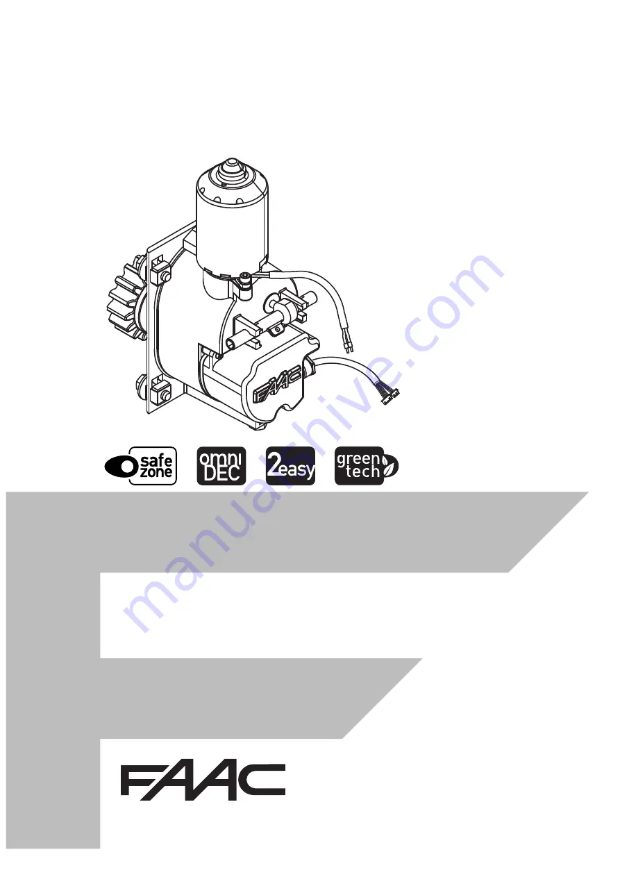
C4000I
Translation of the original instructions
Page 1: ...C4000I Translation of the original instructions ...
Page 2: ...ed No part of this manual may be reproduced archived distributed to third parties nor copied in any other way in any format and with any means be it electronic mechanicalorbyphotocopying withoutpriorwrittenauthorisationbyFAACS p A All names and trademarks mentioned are the property of their respective ma nufacturers Customers may make copies exclusively for their own use This manual was published ...
Page 3: ...chinery Description Gearmotor for sliding gates Model C4000I The essential requirements of the Machinery Directive 2006 42 EC including all applicable amendments that have been applied and fulfilled are as follows 1 1 2 1 1 3 1 1 5 1 2 1 1 2 5 1 2 6 1 3 8 1 1 3 9 1 4 1 1 5 1 1 5 5 1 5 6 1 5 8 1 5 9 1 5 10 1 5 11 1 5 13 1 6 1 1 6 4 1 7 2 1 7 4 2 1 7 4 3 and that the relevant technical documentation...
Page 4: ...4 Install the cable glands 22 5 5 Install the electronic board enclosure 23 With enclosure mounting bracket 23 Without enclosure mounting bracket 24 6 ELECTRONIC INSTALLATION 25 6 1 E4000I components 25 6 2 Connections 27 Board power supply cable 27 Motor 27 Encoder 27 Bus devices 27 Control devices 27 Output 24 V OUT 28 Flashing light 28 Mains power cable not supplied 28 XF radio module 28 XBAT 2...
Page 5: ...lls 38 11 Addressing control devices 39 12 Upload from USB functions 42 13 DOWNLOAD functions from USB 42 14 Scheduled maintenance 45 11 UPLOAD DOWNLOAD FROM TO USB DEVICE 42 Upload 42 Download 42 12 DIAGNOSTICS 43 12 1 LEDs check 43 12 2 Automation system status check 43 12 3 Encoder operation check 43 12 4 Alarms 43 12 5 Errors 44 12 6 Check firmware version 44 13 MAINTENANCE 45 13 1 Routine mai...
Page 6: ... no liability for the reliability and or completeness of the above instructions As such the manufacturer of the machine must carry out all the activities required by the Machinery Directive and the corresponding harmonisedstandardsonthebasisoftheactualcondi tionofthelocationsandstructureswheretheproduct C4000I will be installed prior to commissioning the machine These activities include the analys...
Page 7: ... HAZARD Cutting hazard due to the presence of sharp compo nents or the use of pointed sharp tools drill SHEARING HAZARD Risk of shearing from moving parts IMPACT HAZARD Risk of impact or crushing due to moving parts FORKLIFTTRUCK IMPACT HAZARD Risk of collision impact with forklift trucks 3 Symbols Personal Protective Equipment Personal protective equipment must be worn to pro tect against hazards...
Page 8: ... requirements in these instructions Installation activities require special work conditions to reduce to the minimum the risks of accidents and serious damage Furthermore the suitable pre cautions must be taken to prevent risks of injury to persons or damage The installer must be in good physical and mental condition aware of and responsible for the hazards that may be generated when using the pro...
Page 9: ...ger 2 4 WASTE DISPOSAL 1 N 1 C4000I gearmotor 2 N 1 fasteners 3 N 1 E4000I electronic board 4 N 1 instructions manual STORAGE Store the product in its original packaging in closed and dry premises protected from the sun and free from dust and aggressive substances Protect from mechanicalstress Ifstoredformorethan3months regularly check the condition of the components and the packaging Storage temp...
Page 10: ...ioning Itisprohibitedtousetheautomationsysteminthe presenceoffaultswhichcouldcompromisesafety It is prohibited to use the automation system with thefixedand ormobileguardsremovedoraltered Do not use the automation system unless the area of operation is free of persons animals or objects Donotenter remainintheareaofoperationofthe automation system while it is moving Do not try to prevent the moveme...
Page 11: ...terminethepo sitions of the gate limit switches without the need for additional external devices In addition the encoder allows the position and speed of the gate to be accu rately controlled thereby obtaining an anti crushing with reverse on obstacle detection function To install systems that have two opposite opening leaves two C4000I should be installed in a Mas ter Slave configuration The C400...
Page 12: ... motor 4 Electric motor cable 5 Side release hex socket 6 Central release lever prepared for remote release 7 Encoder 8 Height adjustment system 9 Encoder cable E4000I 10 Enclosure 11 Enclosure fastening screws 12 Boards 13 Enclosure cover ENCLOSURE MOUNTING BRACKET 14 This way up arrow 15 Removable bush 16 Emergency battery fitting optional 17 Board bracket fitting 18 Enclosure mounting tab ...
Page 13: ... 4 5 C4000I 13 532100 Rev A 142 90 2 110 120 7 7 7 7 260 115 48 5 93 110 52 4 68 8 70 61 100 197 6 34 34 190 388 220 113 110 400 Translation of the original instructions ENGLISH 3 8 DIMENSIONS ...
Page 14: ... it slide freely Do not leave the gate with the release engaged after moving it manually restore automatic operation The gate can be released from either side of the column RELEASE PROCEDURE 1 Insert the release device and rotate it a quarter turn as shown in figure 6 1 2 Move the barrier manually RESTORING AUTOMATIC OPERATION 1 Insertthereleasedeviceandrotateitaquarter turn as shown in figure 6 2...
Page 15: ... rollersandbearingsingoodcondition lubricated and free from play or friction Presence of external mechanical limit stops to limit the travel of the leaf when opening and clo sing The stops must be suitably sized and solidly fastened so that they resist any impact of the leaf in the event of improper use leaf pushed and left to slide freely The mechanical limit stops must be positioned at 50 mm bey...
Page 16: ...2 40 80 110 34 34 Translation of the original instructions ENGLISH 4 2 PREPARING THE COLUMN Thedimensions holepositionsandthedooropeningofthecolumnmustbecorrect Thedimensionsshownrefertothe internal dimensions of the column If the rack has already been mounted follow the installation specifications 5 3 INSTALLATION WITH ENCLOSURE MOUNTING BRACKET INSTALLATION WITHOUT ENCLOSURE MOUNTING BRACKET ...
Page 17: ...Rev A E 113 6 A E 110 6 B 720 110 A ø13 75 15 4 40 3 A 40 E 95 5 Translation of the original instructions ENGLISH DOOR OPENING MEASUREMENTS GATE RELEASE SLOT POSITION The gate release slot can be on either side of the column ...
Page 18: ...has to be installed for the cables that connect the two electronic boards Check buried cable plans to ensure that there are no other electrical cables in proximity to the planned digging drilling locations to prevent the risk of electrocution Check that there are no pipes in the vicinity as well The external electronic board must be housed in an enclosure that has a minimum IP 44 protection rating...
Page 19: ...mple is an illustration only and is just one of the possible applications of the C4000I 10 Example system Minimum wire cross section 1 Mains power supply 3G 1 5 sq mm 2 Junction box 3 Key button 4G 1 5 sq mm 4 Pair of photocells 5 Flashing light 6 Board enclosure and circuit breaker 7 Mechanical stop 8 Gearmotor C4000I ...
Page 20: ...RIVERofthespecifiedsize 6 8 6 8 TORX SCREWDRIVER of the size indicated 6 8 ELECTRICIAN S SCISSORS WIRE STRIPPERS 6 8 METAL DRILL BITS of the specified size 6 8 TOOL withTORQUE ADJUSTMENT Where necessary for safety a torque wrench with the specified tightening torque will be shown FASTENINGTORQUEVALUE ThetorquewrenchandthetighteningtorqueinNmis showninthefigures E g SPANNER6setat2 5Nm 6 2 5 Nm The ...
Page 21: ...gearmotor in the installation column so that the holes match up with the cage nuts 12 DO NOT lift the motor by the cables Support it from its base 3 To make the following steps easier the gearmotor can be kept at the fixing height by loosening the fastening screw until it rests on the ground 4 Fix the gearmotor to the column making sure that you fit the washer and the split washer in the correct o...
Page 22: ...e entire stroke 14 1 the rack sections must not be welded together or to the spacers the rack must slide within the width of the pinion along its entire length 14 2 there must be no friction Do not use grease or other lubricants between the rack and the pinion 5 4 INSTALL THE CABLE GLANDS RISKS PERSONAL PROTECTIVE EQUIPMENT 1 Unscrew the enclosure cover screws 2 Remove the cover 3 Drill out the bl...
Page 23: ...an 110x113 LxP 1 16 Removethebushes2 themountingbracket fitting1andtheemergencybatteryfitting3 Keep them to one side for the following procedures 2 Insert the bush 2 into the housing 4 3 Fasten the mounting bracket fitting 1 17 1 onto the base of the enclosure using the 2 screws provided 4 Fasten the mounting bracket to the column using the previously drilled holes with 3 screws and 3 nuts not sup...
Page 24: ...RACKET RISKS PERSONAL PROTECTIVE EQUIPMENT The enclosure can be installed without using the mounting bracket in columns having an internal dimension of 110 x110 or greater 1 Using a screwdriver punch out the knockouts on the board enclosure 20 1 2 Fasten the enclosure to the column via the previ ously drilled holes using the screws and nuts not supplied 20 2 ...
Page 25: ...ard for accessories J7 Terminal board for output OUT J9 Terminal board for flashing light J10 BUS 2easy terminal board J12 Connector for USB device J14 Connector for encoder J15 Connector for encoder J19 Board power cable connector J20 Terminal board for motor F1 Board protection fuse F1 F6 3 A DL1 Board power on LED DL2 Microprocessor power on LED DL3 BUS 2easy BUS MON diagnostic signalling LED D...
Page 26: ... OUT OUT LAMP LAMP 24V 100mA max OPEN A OPEN B SAFE OP SAFE CL GND 24 24 STOP CLOSE 24V 1A max MOT1 MOT1 BUS BUS J6 J7 J2 J19 DL4 DL5 DL6 DL3 F1 J9 J3 J10 J20 J14 J12 J15 F DL1 DL2 DL7 DL8 DL10 15 DL16 DISPLAY Translation of the original instructions ENGLISH BOARD POWER SUPPLY UNIT ...
Page 27: ...onnected in order for the automation system to operate BUS DEVICES If no BUS 2easy devices are used leave the BUS 2easy terminal board free For connecting and assigning addresses see 38 CONTROL DEVICES 1 Route the control devices cable through one of the cableglandsatthebaseoftheenclosure Ifnecessary use one of those on the cover of the enclosure 2 Connect the devices to terminal board J6 of the b...
Page 28: ...D Accessories power supply negative and common contact 1 A max 8 9 Accessories power supply positive 24 V 1 A max If safety devices are NOT connected With Fail Safe enabled bridge the terminals SAFE OP and SAFE CL to OUT FAIL SAFE With Fail Safe disabled bridge the terminals SAFE OP and SAFE CL with GND OUTPUT 24 V OUT Do not exceed the maximum load of 100 mA The activation of the output can be co...
Page 29: ...ompleted it is recommended to save the settings 11 7 1 PROGRAMMING BASIC PROGRAMMING List of basic functions 8 1 Press and hold down F until the first basic function appears Each function is displayed as long as F remains pressed F 2 Release the value of the function appears default or programmed F 3 Use the or button to modify the value 4 PressFtoconfirmthevaluedisplayed Go to the next function T...
Page 30: ... min and 50 sec 20 Basic function Default Pb PAUSE TIME B displayed only if an automatic logic is selected It is the partial opening pause time Adjustable from 00 to 59 sec in 1 second steps If 59 is exceeded the display changes to indicate minutesandtensofseconds separatedbyapoint andcanbeadjustedinstepsof10seconds uptoa maximum of 9 5 minutes E g If the display indicates 2 5 the time is 2 min an...
Page 31: ...thephotocellshavedisen gaged no immediate reverse no oP OPENING PHOTOCELLS Enable this function if you wish the opening photocells to stop the movement and reverse the gate during closing Normally with this function disabled if the photocells are triggered during opening movement resumes when they become disengaged Y immediate reverse during closing No movement resumes when disengaged no IP PARTIA...
Page 32: ...ber of cycles carried out is greater than 99 990 the next two functions nc and nd will display 99 and 99 respectively no Advanced function Default nc CYCLE PROGRAMMING THOUSANDS If AS Y the display will indicate the number of thousands of cycles after which the maintenance alert starts can be set from 0 to 99 IfAS no thedisplaywillindicatethenumberof thousandsofcyclesperformed Thevaluedisplayed is...
Page 33: ...trol must be activated intentionally and the gate must be visible OPEN maintained opens the gate CLOSE maintained closes the gate If the photocells are triggered movement is stopped 7 3 SET UP The set up procedure enables the limit switch posi tions to be memorised Theset upproceduremustdetectastrokeofbetween 0 5 and 12 m The system needs to be set up When the automation system is first started Wh...
Page 34: ...OR Before installing the board enclosure cover and door you must have completed the start up procedure checked that the installed devices are working properly 1 Install the enclosure cover 27 2 Install the door on the column 8 3 FINAL OPERATIONS 1 Highlight all areas with adequate warning signs in which there are still residual risks even if all possible safety measures having been adopted 2 Place...
Page 35: ... of the XBAT 24 battery is 72 hours 1 Remove the board 29 1 2 Fastentheemergencybatteryfittingtotheenclo sure 29 2 3 Place the battery into the enclosure 4 Turnthebatteryfittingsothatitisvertical inorder to secure the battery onto the support 5 ConnecttheconnectoroftheXBAT24toconnector J2 of the board Disconnect the emergency battery if the automation system is taken out of use 9 3 XF RADIO MODULE...
Page 36: ...ing mode that has been set LC RC MEMORISING THE FIRST RADIO CONTROL 1 Press and hold down the button OPEN A programming or OPEN B CLOSE program ming After pressing the button for about 5 seconds thecorrespondingradioLED DL4orDL5 will start to flash to indicate that the radio code learning phase has started 2 Releasethebutton theE4000Inowremainsinthe learning phase for approximately 20 seconds 3 Ma...
Page 37: ...hesameON OFF combination as the 12 DIP switches on the radio control that has been memorised DELETING RADIO CONTROLS FROM MEMORY This procedure cannot be reversed It will delete ALL radio control codes that have been memorised as OPEN A and OPEN B CLOSE The deletion procedure is only active in the gate status display mode 1 Press and hold down the button Afterpressingthebuttonforabout5seconds LED ...
Page 38: ...lls wireless safety edge system control devices If no BUS 2easy accessories are used leave the BUS 2easy connector free Do not bridge CONNECTION 1 Route the cable of the BUS 2easy devices through one of the cable glands at the base of the enclo sure If necessary use one of those on the board enclosure cover 2 Connect any BUS 2easy devices photocells wire less safety edge system and controls to ter...
Page 39: ...temtransmitterandreceiver thestatusof the bus on the display and the automated system operate according to the type of edge installed CONTROL DEVICES 1 PositiontheDIPswitchestoassignthecommands Stop NC also generates a stop when the device is disconnected A command e g OPEN A_1 must be used on only one of the connected devices 11 Addressing control devices 0 0 0 0 Open A_1 0 0 0 1 Open A_2 0 0 1 0...
Page 40: ...ine monitoring LED always on off with board in Sleep mode Line short circuited Device error check the ERROR LED Board in Sleep mode Registered device verification procedure 1 Select parameter bu in Basic programming After registering one or more devices bu displays segment 13 on 2 Press the button and keep it pressed the seg ments relative to the registered devices will come on Each segment of the...
Page 41: ...US 2easy polar ised connection 32 2 Connect the devices see 27 The inputs for the command devices are disabled on the Slave board Connections Master Slave Power supply Motor Encoder Control devices Outputs Flashing light 3 The BUS 2easy devices can be connected to the Master or to the Slave board The devices must be registered on the Master gearmotor SLAVE GEARMOTOR CONFIGURATION 1 Switch on the S...
Page 42: ...tension name_001 extension name_003 extension Or saves the file by overwriting an existing file with the same name on the USB device The file is saved as name extension 6 ThemodedisplayedcanbeusedrunbypressingF while it is running flashes on the display and the USB LED on the board flashes 7 When finished the display will show Y if the download was completed successfully no if there were errors 8 ...
Page 43: ...gate opens The flashing point betweenthetwolettersindicatesthattheencoder is operating correctly 3 Keepthe buttonpressed Thedisplayindicates cL and the gate closes The flashing point be tween the two letters indicates that the encoder is operating correctly 12 4 ALARMS The alarms provide information regarding the condi tion or current phase of the automation system and any malfunctions that do not...
Page 44: ...re not two pairs of devices with the same address 09 BUS 2easy output short circuited Check the connections of the BUS 2easy devices that are con nected and registered 12 Call BUS 2easy Check the operation of the BUS devices Repeat the acquisition procedure if necessary 13 FAIL SAFE Checkthatthesafetydevices edg es are working correctly 14 Configuration error Check the board configuration opening ...
Page 45: ...n ensuring there is no damage cracking or subsidence 12 Check the gate s area of movement ensuring it is free from obstacles objectsordepositswhichwouldreducetheeffec tiveness of the safety measures 12 Checkthattherearenogapsintheperimeterfenceandthat any protective grilles in the area where it overlaps with the mobile leaf are intact 12 Ensure that there are no sharp protrusions which could repre...
Page 46: ... the set logic when using the various control devices 12 Check that the gate moves correctly smooth regular and without abnormal noise 12 Check that both the opening and closing speed are correct and that the stop positions and slow downs provided for are respected 12 Check that the manual release operates correctly when the release mechanism is activated it must only be possible to move the gate ...
Page 47: ...not allow the devices to be used by anyone who is not specifically authorised and trained to do so Donotallowthedevicestobecontrolledbychildren or persons with mental and physical deficiencies un lesstheyaresupervisedbyanadultwhoisresponsible for their safety Do not use the automation with the fixed and or mobile guards removed or altered Do not use the automation in the presence of faults which c...
Page 48: ... 34 C4000I 48 532100 Rev A 1 2 Translation of the original instructions ENGLISH ...
Page 49: ...FAAC S p A Soc Unipersonale Via Calari 10 40069 Zola Predosa BOLOGNA ITALY Tel 39 051 61724 Fax 39 051 09 57 820 www faac it www faacgroup com C4000I 49 532100 Rev A ...