ETEL Doc. - Operation & Software Manual # DSC2P 903 / Ver. F / 3/6/05
Chapter C: System functions
Operation & Software Manual
Direct Drives & Systems
115
• Encoder's home/limit switch. In that case, they are integrated in the encoder and the controller allows the
user to connect them directly to the EHO and ELS pins of the encoder's connector (refer to the
corresponding
'Hardware Manual'
for more information about these pins).
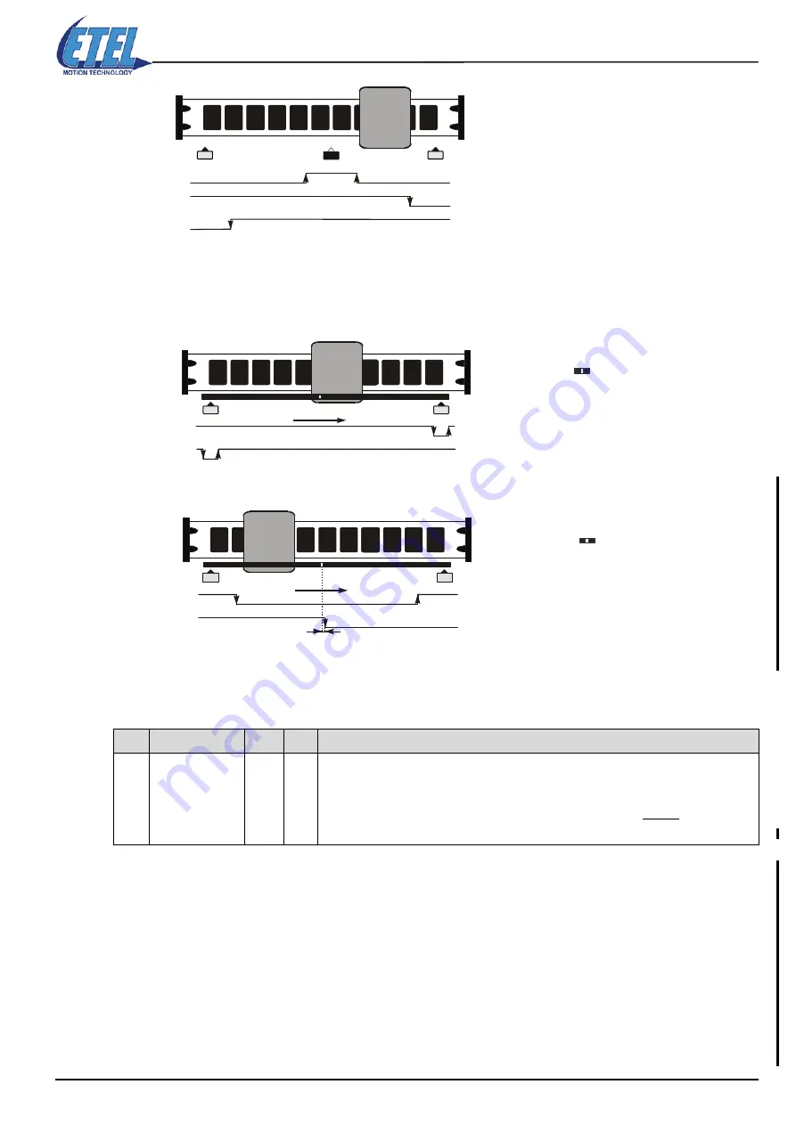
•If there are two limit switches, generally called L1 for the negative one and L2 for the positive one, they
can be connected as follows:
•If there are one limit switch and one homing switch(*), generally called L for the limit switch and H for
the home switch, they can be connected as follows:
(*): The home switch is positioned within a gap of 1mm.
Bit# 1, 2 and 3 of parameter K32 allow the user to invert either the home switch or the limit switch (which means
to choose the polarity) depending on the homing mode selected by parameter K40.
Remark:
If the bit 0 is enabled, the controller gives a
SWITCH LIMIT
error (M64=30) when the limit switches
are reached during a movement (except during the IND or SLS command). This error is generated
only if the controller is in ’Power On’.
To reset the error
when K61=1
, the following procedure is recommended:
- Reset the error (with RST.<axis> command)
- Send the command: PWR.<axis>=1
- Move the motor out of the limit switch (with POS.<axis> command).
To reset the error
when K61
≠
1
, the following procedure is recommended:
- Clear bit# 0 of K32 (otherwise during the next ’Power On’, the same error will come back)
- Reset the error (with RST.<axis> command)
- Send the command: PWR.<axis>=1
- Move the motor out of the limit switch (with POS.<axis> command)
- Set to 1 the bit# 0 of parameter K32
K
Name
Value Bit #
Comment
K32
Limit switch and
home switch
inversion
1
2
4
8
16
32
0
1
2
3
4
5
Enables the errors when using the limit switches.
Inverts the polarity of the home switch.
Inverts the polarity of the limit switches from the encoder.
Inverts the polarity of the limit switches from the digital inputs.
Enables the use of the dynamic braking controlled by the transistor (
DSCDL
)
Enables the limitation of parameters K60 and K31 according to the state of the digital inputs.
Home switch status given by DIN2
Positive limit switch status given by DIN10
Negative limit switch status given by DIN9
MOTOR
Positive limit switch (L2) status connected to EHO pin
Negative limit switch (L1) status connected to ELS pin
+
Reference mark
MOTOR
Limit switch (L) status connected to ELS pin
Home switch (H) status connected to EHO pin
+
1mm
Reference mark
MOTOR


