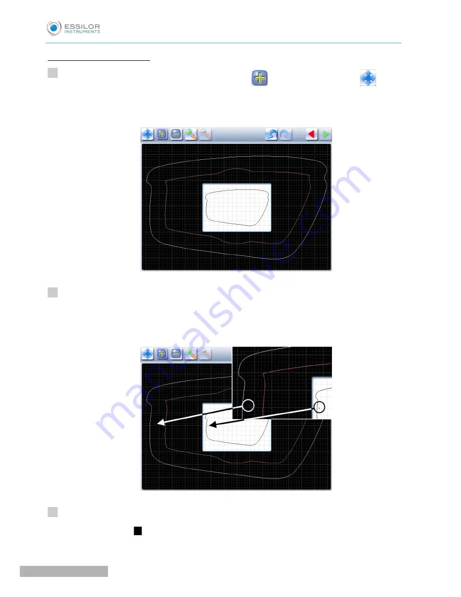
Create the step bevel trajectory
From the customized screen for the step outline, press
to select the shape, then
to add
points.
The following screen will appear:
Press and hold the stylus to set the first point of the step bevel trajectory.
An audible signal informs you that the first point is registered.
The point is displayed in blue within the work space and in the display window on scale 1.
Press and hold the stylus to set the second point of the step bevel trajectory.
A green segment (
) is created between the points.
>
>
>
>
1
2
3
Pro-E 600_Pro-E 700 > v1 -10.18
86
U
SER
M
ANUAL
> II. E
DGING
A
LENS
Summary of Contents for Pro-E 600 edger
Page 1: ...User Manual...
Page 2: ......
Page 6: ......
Page 8: ......
Page 9: ...I FIRST STEPS WITH PRO E...
Page 10: ...Pro E 600_Pro E 700 v1 10 18 10 USER MANUAL I FIRST STEPS WITH PRO E...
Page 17: ...II EDGING A LENS...
Page 18: ...Pro E 600_Pro E 700 v1 10 18 18 USER MANUAL II EDGING A LENS...
Page 127: ...III PREPARING A DRILLED JOB...
Page 128: ...Pro E 600_Pro E 700 v1 10 18 128 USER MANUAL III PREPARING A DRILLED JOB...
Page 136: ......
Page 137: ...IV CONFIGURING THE EDGER...
Page 138: ...Pro E 600_Pro E 700 v1 10 18 138 USER MANUAL IV CONFIGURING THE EDGER...
Page 151: ...V MAINTENANCE SERVICING...
Page 152: ...Pro E 600_Pro E 700 v1 10 18 152 USER MANUAL V MAINTENANCE SERVICING...
Page 181: ...TECHNICAL DATA...
Page 182: ...Pro E 600_Pro E 700 v1 10 18 182 USER MANUAL TECHNICAL DATA...
Page 186: ......
Page 187: ...GENERAL INFORMATION...
Page 188: ...Pro E 600_Pro E 700 v1 10 18 188 USER MANUAL GENERAL INFORMATION...
Page 194: ......
Page 195: ...GLOSSARY...


