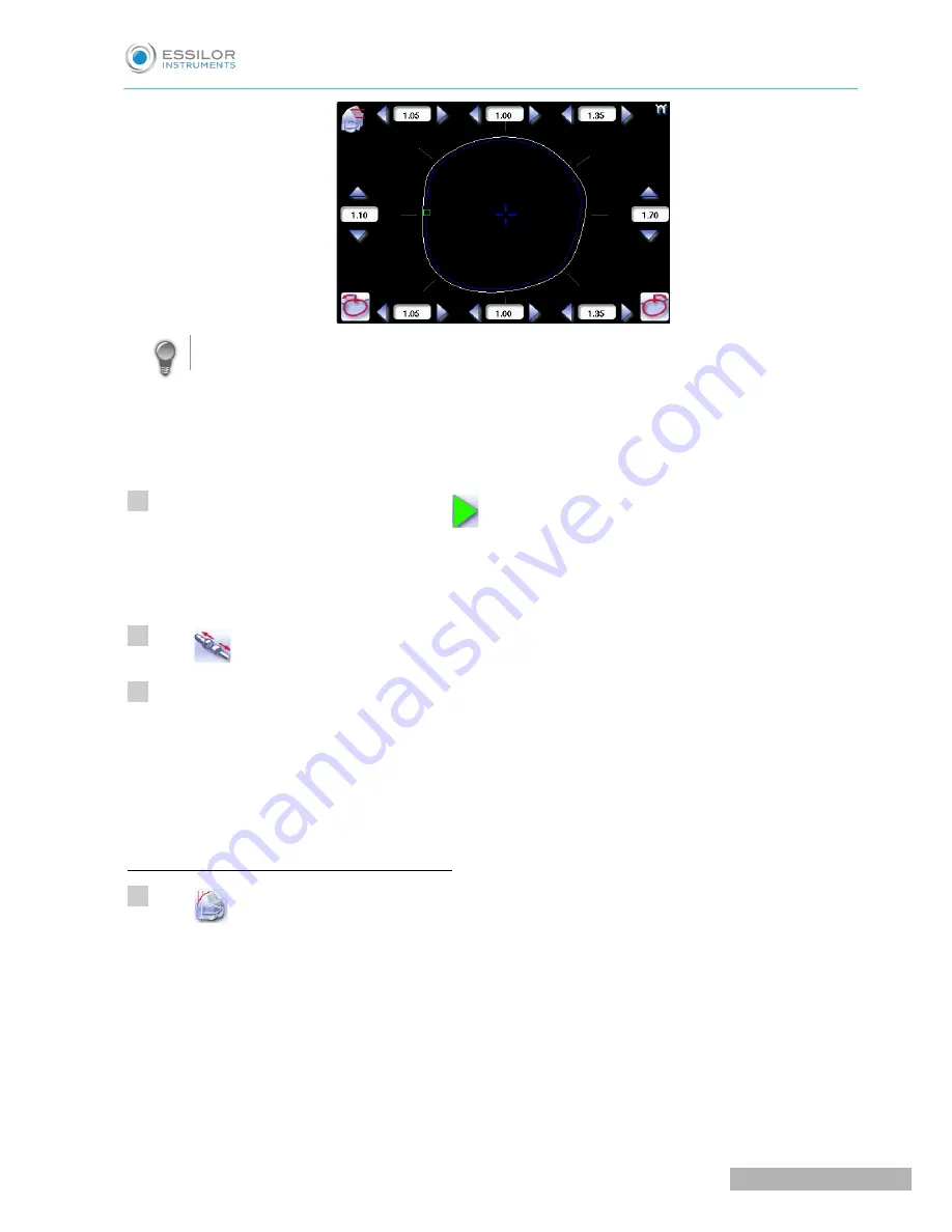
Move the cursor along the shape to see the bevel profile in the zoom window.
The edger calculates the shelf bevel value to be applied between each of the four points in each area.
The bevel trajectory on the rear surface is modified in the work screen. The result can be viewed in
the zoom window.
Press the “cycle start” button (front face) or
.
The edging cycle starts.
When the edging cycle is finished, the retouch screen is displayed.
Press
to release the lens.
If necessary, retouch the lens.
Otherwise, start edging the second lens. Select the lens directly on the screen, on the left or right of the
work area.
The edging screen for the second lens is displayed. All finishes chosen and the modifications made
are kept.
High-base bevel in “front surface tracking” mode
Press
to select the bevel in “front surface tracking” mode.
>
>
>
>
>
4
5
6
1
U
SER
M
ANUAL
> II. E
DGING
A
LENS
37
Pro-E 600_Pro-E 700 > v1 -10.18
Summary of Contents for Pro-E 600 edger
Page 1: ...User Manual...
Page 2: ......
Page 6: ......
Page 8: ......
Page 9: ...I FIRST STEPS WITH PRO E...
Page 10: ...Pro E 600_Pro E 700 v1 10 18 10 USER MANUAL I FIRST STEPS WITH PRO E...
Page 17: ...II EDGING A LENS...
Page 18: ...Pro E 600_Pro E 700 v1 10 18 18 USER MANUAL II EDGING A LENS...
Page 127: ...III PREPARING A DRILLED JOB...
Page 128: ...Pro E 600_Pro E 700 v1 10 18 128 USER MANUAL III PREPARING A DRILLED JOB...
Page 136: ......
Page 137: ...IV CONFIGURING THE EDGER...
Page 138: ...Pro E 600_Pro E 700 v1 10 18 138 USER MANUAL IV CONFIGURING THE EDGER...
Page 151: ...V MAINTENANCE SERVICING...
Page 152: ...Pro E 600_Pro E 700 v1 10 18 152 USER MANUAL V MAINTENANCE SERVICING...
Page 181: ...TECHNICAL DATA...
Page 182: ...Pro E 600_Pro E 700 v1 10 18 182 USER MANUAL TECHNICAL DATA...
Page 186: ......
Page 187: ...GENERAL INFORMATION...
Page 188: ...Pro E 600_Pro E 700 v1 10 18 188 USER MANUAL GENERAL INFORMATION...
Page 194: ......
Page 195: ...GLOSSARY...


