background image

This section describes the procedure to follow for tracing rimmed frames including high-base frames:

Symmetric binocular

&

 mechanical tracing of a rimmed frame

Asymmetric binocular

&

 tracing of a rimmed frame

Monocular tracing of a rimmed frame

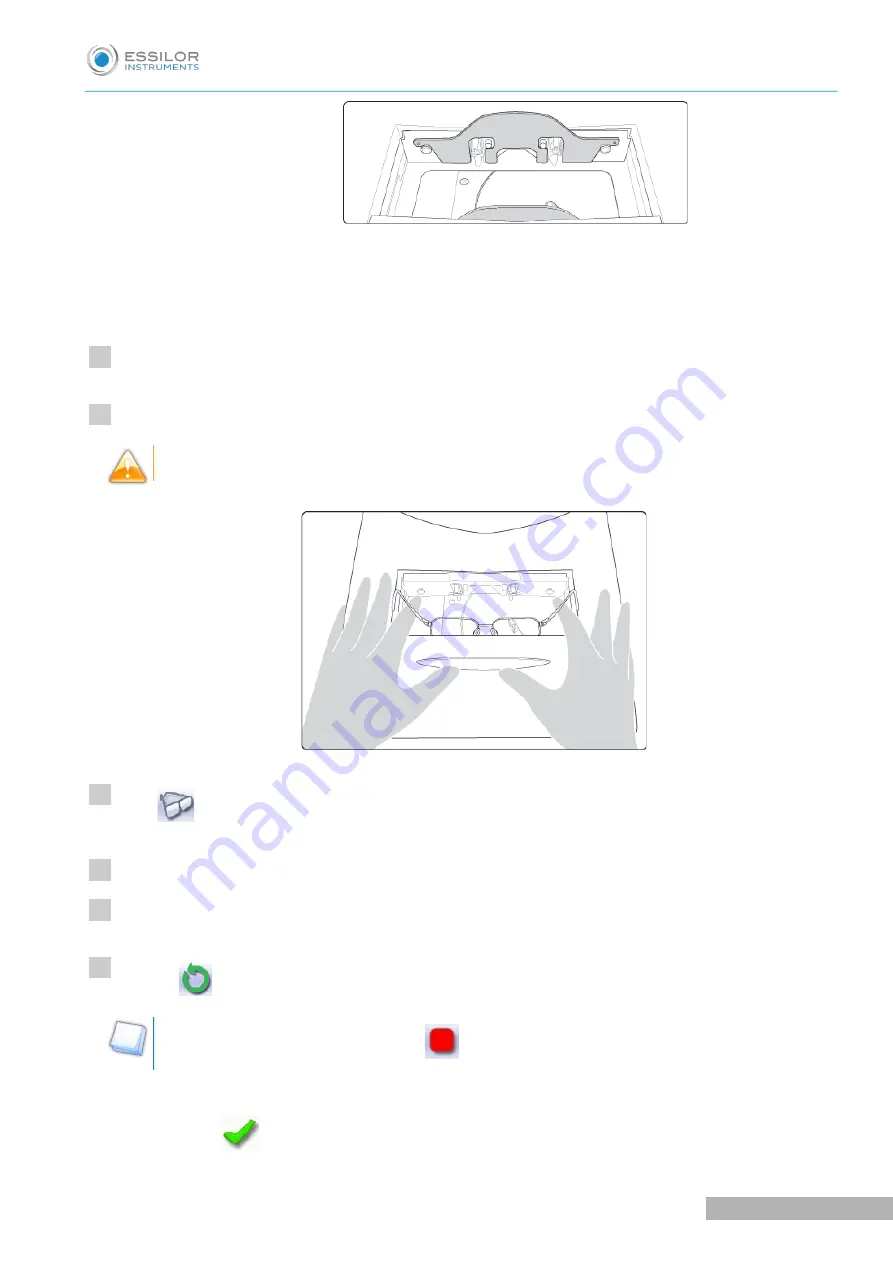
Place the frame in the tracing table, between the two clamps located opposite you.

Gently close the jaw to hold the frame. 

Optyl

&

 frames: take care not to flatten the frame by closing the jaws.

Press 

 to select the type of rimmed frame.

Select the required type of tracing.

Select the frame material.

Press on 

 to start the tracing cycle.

To interrupt tracing at any time, press 

.

If you selected a monocular tracing, the numeric keypad is displayed. Enter the D-dimension value,

then press 

 to confirm.

>

1

2

3

4

5

6

U

SER

 M

ANUAL

> II. T

RACING


29

Pro-B 300 > v1.0 - 03.19

Summary of Contents for Pro-B 300

Page 1: ...User Manual...

Page 2: ......

Page 3: ...g the curve and the frame base after monocular tracing 38 III CENTERING A LENS 41 1 Centering environment 42 a Legend screen 42 b Centering modes 44 c Using the tripods 45 d Centering help 45 2 Center...

Page 4: ...evice 100 a Time date and language 100 b Connections 101 c Screensaver 102 2 Optimize the device s centering function 102 3 Customizing the device 104 a Working mode and measurement display 104 b Dece...

Page 5: ...NERAL INFORMATION 131 1 Symbols 132 2 Modifications 132 3 Declaration of conformity 133 4 Copyright 133 5 Materials and products 133 6 Safety instructions 133 7 Electromagnetic waves 134 GLOSSARY 135...

Page 6: ......

Page 7: ...TION To take full advantage of the features of your Pro B 300 tracer centerer blocker or centerer blocker we strongly recommend that you read the documentation USER MANUAL INTRODUCTION 7 Pro B 300 v1...

Page 8: ......

Page 9: ...I FIRST STEPS...

Page 10: ...IVE DIAGRAMS This section contains descriptions and a list of accessories for the tracer centerer blocker and centerer blocker Tracer centerer blocker 1 Screen 2 ON OFF button 3 Blocking arm 4 Centeri...

Page 11: ...18x14 mm posiblocks Transport wedges to be kept Use accessories Stylus Standard tripod High base tripod Recut accessory Small B dimension wedges quantity 2 White felt tip marker Roll of 22 mm pads Rol...

Page 12: ...vice is turned on make sure the tracing table is empty depending on the version To switch on the tracer press the main switch located at the rear of the machine Press the ON OFF button under the touch...

Page 13: ...ch screen For further information refer to the section Maintenance and servicing Check and calibrate Calibrate the touch screen F p 121 Never press hard on the screen as this could break it Never pres...

Page 14: ...ers Job list Collection list d Tracing screen Tracer centerer blocker Main menus on the tracer centerer blocker screen 1 Work screen indicator 2 Job information 3 Settings 4 Connected devices Pro B 30...

Page 15: ...of the screen relates to the left eye 6 Work area 7 Function buttons Machine shutdown Tracing Centering Shape management 8 Actions available for the current screen 9 Tracing cycle initialization Cente...

Page 16: ...of the screen relates to the left eye 6 Work area 7 Function buttons Machine shutdown Tracing Centering Shape management 8 Actions available for the current screen 9 Tracing cycle initialization Detai...

Page 17: ...II TRACING...

Page 18: ...tern a demo lens or recut lens F p 32 1 THE TRACING ENVIRONMENT This section describes the tracing screen and explains how to manage the jobs Description of the tracing screen F p 18 Jobs and working...

Page 19: ...Frame materials or type of optical tracing For mechanical tracing of a frame Metal frame high precision tracing with feeling of the groove cross section Plastic frame Optyl frame for particularly flex...

Page 20: ...cular view 9 New Job For more information on jobs refer to the section Tracing Shape management and storage F p 23 10 Tracing cycle initialization Centerer blocker 1 Dimensions display A A dimension B...

Page 21: ...n be managed in two ways Saving allocate an ID and a reference to the job to save it and re use it later Automatic job archiving Mandatory in the tracing tracing work mode Without saving working in co...

Page 22: ...ssion The tracings are saved with the job number you have allocated to them Shape modification centering blocking and edging of the lenses are processed later All jobs must be saved You can access the...

Page 23: ...omplete 1 Press to display the binocular view The binocular view is displayed 2 Position the frame in front of the screen against the faceplate to check its shape and centering 3 Press to return to th...

Page 24: ...ed job 3 Select the eye to be displayed in the preview 4 Shape preview 5 Information concerning the lens shape and frame A B and D dimensions Frame base Wrap angle Material of the frame pattern demo l...

Page 25: ...ss on the button then select jobs 1 5 7 Only jobs 1 5 and 7 are selected Press to select a group of consecutive jobs in the list then select the first and last job in the group Example Press on the bu...

Page 26: ...der optional the job is saved to the job list To create a job use the alphanumeric keypad and follow the procedure below From the tracing screen press in the action bar to create a new job The alphanu...

Page 27: ...rning your job type The symbol is displayed at the bottom right of the job ID while the job is being modified It disappears once the job has been saved The symbol is displayed into high right hand sid...

Page 28: ...ocedure below From the tracing screen press in the action bar to create a new job The alphanumeric keypad is displayed For more information on keyboard entry and use refer to the section First steps S...

Page 29: ...o clamps located opposite you Gently close the jaw to hold the frame Optyl frames take care not to flatten the frame by closing the jaws Press to select the type of rimmed frame Select the required ty...

Page 30: ...bles you to trace a high base frame if the standard rimmed frame tracing fails Tracing of a high base frame is done in two stages The frame is placed in the tracing table and mechanical tracing is don...

Page 31: ...t eye is finished a message is displayed Position the frame to trace the second eye Press to start tracing the second eye The following screen is displayed Measuring the wrap angle and completing the...

Page 32: ...ng tracing mode In tracing tracing mode the result of the tracing is displayed in the work area of the tracing screen For more information on working modes refer to the section Tracing Tracing environ...

Page 33: ...permanent felt tip marker with either three focimeter dots or a horizontal line which must not touch the edges of the lens a space of at least 5 mm is required Tracing Place the pattern or demo lens...

Page 34: ...more information refer to the section Preparing a drilled job F p 79 Press to go to the centering screen Tracing tracing mode In tracing tracing mode the result of the tracing is displayed in the wor...

Page 35: ...holder tip 8 Holding screw Attaching a recut lens or demo lens to the pattern holder Block the lens in the boxing center making sure it is properly centered Insert the blocked lens in the posiblock cl...

Page 36: ...pattern nose to the right for a right lens and to the left for a left lens pattern holder posiblock positioner towards the bottom of the pattern Press on the knurled knob screwing it until the patter...

Page 37: ...pattern holder The buttons and are displayed Select the eye to be traced The numeric keypad is displayed Enter the D dimension value then press to confirm The tracing result is displayed in the center...

Page 38: ...tracing of a pattern recut lens or demo lens Prerequisite before entering the wrap angle and frame base one of the following operations must be performed Optical tracing of a pattern a demo lens or a...

Page 39: ...ange it using the numeric keypad The wrap angle value is changed Select the of frame base value to modify it The value is displayed in red Use the and buttons to modify the frame base value You can al...

Page 40: ......

Page 41: ...III CENTERING A LENS...

Page 42: ...entering a lens for a high base frame F p 66 This chapter also describes the lens blocking F p 67 procedure 1 CENTERING ENVIRONMENT This section describes the centering screen and the various centerin...

Page 43: ...or without recut accessory High base tripod 8 Lens type selection Single vision lens Progressive lens Bifocal lens Executive lens Mid distance lens 9 Centering mode selection Centering using three fo...

Page 44: ...n limit appears on the screen If the B dimension value is less than an X value previously determined in the configuration screen a warning appears on the icon and the text is displayed in red Always b...

Page 45: ...marks of the lenses according to the centering mode selected Two types of help are available for the following lenses Single vision Progressive ARROWED HELP DISCRETE HELP Positioning indicators help...

Page 46: ...e created Place the stickers recommended by the manufacturer on hydrophobic lenses This section describes the procedures for centering a single vision lens Centering using three focimeter dots F p 46...

Page 47: ...gh base tripod for a high base lens Place the recut accessory in the center of the standard tripod for a small lens Position the lens on the tripod If centering help is enabled yellow indicators are d...

Page 48: ...HELP WITH DISCRETE HELP The lens is centered and ready to be blocked To block the lens refer to the section Centering a lens Blocking a lens F p 67 b Centering a single vision lens using re marked mic...

Page 49: ...of single vision lens Press to select the centering mode starting at the micro engravings The centering target is displayed Enter the half PD and pupillary height The target moves Make sure that the...

Page 50: ...Centering help see the section Center a lens centering Environment centering help F p 45 WITH ARROWED HELP WITH DISCRETE HELP Move the lens slowly until the micro engravings are perfectly aligned on...

Page 51: ...manufacturer on hydrophobic lenses This section describes the procedures for centering a progressive lens Centering using re marked micro engravings F p 51 Centering using manufacturer markings mode...

Page 52: ...he PRP prismatic reference point and the centering cross if necessary This value is configured to 4 mm by default for Essilor progressive lenses This can vary depending on the lens manufacturer The ta...

Page 53: ...a lens centering Environment centering help F p 45 WITH ARROWED HELP WITH DISCRETE HELP Move the lens slowly until the micro engravings are Aligned on the graduated axis mark Symmetrical with respect...

Page 54: ...he following markings 1 Far vision mark If centering help is enabled the cross must contain at least three branches 2 Centering marks If centering help is enabled the marking must include at least two...

Page 55: ...erence point and the centering cross if necessary This value is configured to 4 mm by default for Essilor progressive lenses This can vary depending on the lens manufacturer The target moves Make sure...

Page 56: ...lp F p 45 WITH ARROWED HELP WITH DISCRETE HELP Move the lens slowly until the manufacturer markings are superimposed on the target If centering help is enabled green indicators are displayed WITH ARRO...

Page 57: ...the manufacturer on hydrophobic lenses This section describes the centering procedure for a bifocal or trifocal lens with a straight curved or round segment Description of the centering target 1 Cente...

Page 58: ...od is inside the centering chamber Use the high base tripod for a high base lens Place the recut accessory in the center of the standard tripod for a small lens Position the lens on the tripod Move th...

Page 59: ...e created Place the stickers recommended by the manufacturer on hydrophobic lenses This section describes the procedure for centering an executive lens Prerequisite The lens must be marked with the fo...

Page 60: ...r far vision and the frame height The target moves Make sure that the standard tripod is inside the centering chamber Use the high base tripod for a high base lens Place the recut accessory in the cen...

Page 61: ...Before centering the lens you must first trace a shape in the centering screen If necessary we recommend the following prior operations Preparing drilling points F p 79 to be created Place the sticke...

Page 62: ...e dots must be between 0 5 and 1 5 mm You are recommended to use the white felt tip marker supplied with the tracer to mark the lens Press to select the type of mid distance lens Press to select the c...

Page 63: ...d is inside the centering chamber Use the high base tripod for a high base lens Place the recut accessory in the center of the standard tripod for a small lens Position the lens on the tripod Move the...

Page 64: ...ross 2 Centering marks Description of the centering target 1 Centering cross white cross and Boxing center blue cross of the shape 2 Centering marks Centering the lens Press to select the type of mid...

Page 65: ...ding on the lens manufacturer The target moves Make sure that the standard tripod is inside the centering chamber Use the high base tripod for a high base lens Place the recut accessory in the center...

Page 66: ...the frame is treated in three dimensions 3D compensation takes into account all frame characteristics x y z curve pantoscopic tilt etc to ensure that the center of the wearer s pupil is at the optica...

Page 67: ...The lens must be centered Use the posiblock adapted to the shape Fit the appropriate pad on the posiblock making sure to align the pad lug with that of the posiblock The pads are non re usable Do not...

Page 68: ...lens is displayed The adjustments made to the PD pupillary height type of lens and centering mode are displayed by default for the second lens Center and block the second lens 4 Pro B 300 v1 0 03 19...

Page 69: ...IV MODIFYING THE LENS SHAPE...

Page 70: ...e from the traced shape and associated drilling points cyan Current shape obtained by symmetry with the traced shape and associated drilling points light red Shape before modification grey Part of the...

Page 71: ...dify the selected value The modification is carried out in 0 5 mm or 1 mm steps depending on the precision settings F p 104 15 Create a new job based on the job displayed 16 Back to the centering scre...

Page 72: ...r tracing modifications are automatically made to both eyes Modifying each dimension or half dimension separately Select the icon showing the part of the shape you wish to decrease or increase A red r...

Page 73: ...gement of the shape Rotating a shape around the boxing center Press to select modification by rotation A red rectangle is displayed around the icon Use the or buttons to rotate the shape clockwise or...

Page 74: ...ions are automatically made to both eyes Select The selection area is delimited by two cursors and The area not affected by the modification is displayed in grey Select the type of modification Modifi...

Page 75: ...sly If you have done an asymmetric binocular tracing you can modify both shapes simultaneously Modification of both eyes simultaneously Modification of each eye separately In symmetric monocular or bi...

Page 76: ...the last modification made to the shape Press twice consecutively to return to the original shape Once the shape is modified press to save and go back to the centering screen 3 ARCHIVING SAVING A SHA...

Page 77: ...cted list You can also give it a different ID Enter a reference for the shape to be saved Press to confirm The shape is archived in a new job with a new ID and is displayed in the shape modification s...

Page 78: ......

Page 79: ...V PREPARING A DRILLED JOB...

Page 80: ...ve carried out lens tracing Optical tracing If you trace a demo lens or a pattern using the optical tracing function the drilling screen is displayed automatically once the tracing is complete Glass l...

Page 81: ...the drill hole entrance point and the edge of the lens X and Y coordinates in relation to the reference drilling point Freezing of the distance between the drilling point and the edge of the lens 5 Vi...

Page 82: ...sitioning of a drilling point Creating a drilling point F p 82 Delete one drilling point F p 84 Dimensioning a drilling point F p 84 Adjusting the position of a drilling point F p 86 The positions of...

Page 83: ...t Press to copy the drilling points from the nasal area to the temporal area and vice versa On the tracer you can configure up to 6 drilling points per side nasal and temporal of a shape Picture mode...

Page 84: ...int is displayed in red Press Two buttons are displayed Press to delete the selected drilling point or to delete all drilling points from the shape The selected drilling point or all drilling points a...

Page 85: ...s If you need to modify several drilling points simultaneously you can group them together provided they are on the same side of the shape nasal side temporal side By default the symbol is displayed e...

Page 86: ...otch the entrance point is always on the side which is furthest away from the edge of the lens For greater precision when you use the virtual mouse or the and buttons press to zoom in on the selected...

Page 87: ...hape nasal side temporal side By default the symbol is displayed each drilling point can be modified individually Press is displayed All future modifications will be applied to all drilling points in...

Page 88: ...erence drilling point Press to the right of its coordinates The selected drilling point is displayed at the top of the list The symbol is displayed on the left of its coordinates The drilling point is...

Page 89: ...shape management screen Select the desired list The drilled jobs in the selected list are displayed Select the desired job as a drilling model The model is displayed in the preview Press to confirm im...

Page 90: ...sion The drilling point settings The drilling point heights in relation to the Boxing center of the shape Y coordinates The distance from reference drilling points in relation to the edge of the lens...

Page 91: ...USER MANUAL V PREPARING A DRILLED JOB 91 Pro B 300 v1 0 03 19...

Page 92: ......

Page 93: ...VI PREPARING LENS EDGING...

Page 94: ...is carried out in the machine configuration screen For more information see the chapter Setting up the tracer centerer blocker Customize tracer working mode and Display Metrics F p 104 1 LEGEND SCREEN...

Page 95: ...with hydrophobic coating 3 Type of finish Bevel Customized bevel Groove Customized groove Flat edge Flat edge and drilling Existing drilling disabled 4 To access the drilling preparation screen 5 Edg...

Page 96: ...r Both lenses are set simultaneously Press to select the lens material The configuration of the edging cycles depends on the type of material An incorrect choice may result in material damage Press to...

Page 97: ...rameter setting and go back to the centering screen or the tracing screen if the option is activated When you call the shape from the edger its edging settings will automatically be retrieved 8 9 USER...

Page 98: ......

Page 99: ...VII TO SET UP THE DEVICE...

Page 100: ...E DEVICE This section describes the procedures to Set the time date and language F p 100 Access the connections and the network F p 101 Configure a screen saver F p 102 a Time date and language To acc...

Page 101: ...his menu from your tracer work screen select The following screen is displayed 1 List of devices connected to the tracer 2 Settings linked to the configuration of the serial port 3 Settings linked to...

Page 102: ...eensaver in seconds 3 Transition Set the transition time between each image in seconds Once the modification is made press to return to the work screen 2 OPTIMIZE THE DEVICE S CENTERING FUNCTION This...

Page 103: ...ars Enter a value that s positive to shift the centering cross to the patient s temple Enter a value that s negative to shift the centering cross to the patient s nose You can also use the and buttons...

Page 104: ...ntration mode F p 106 Customising the action bar F p 107 a Working mode and measurement display This menu allows you to customize the working mode and display accuracy on the device To access this men...

Page 105: ...g 7 Preparation of the lens for edging Select the display or not for the menu Preparation of the lens for edging 8 Working mode Select the Working mode by default if the display of the menu Preparatio...

Page 106: ...d in relation to the lowest point on the frame 2 Datum mode PD Datum Height The wearer s pupillary height is calculated in relation to the point of intersection with the frame 3 Y mode PD Y Y This val...

Page 107: ...centering help To access the customization menu of the action bar from your work screen select The following screen is displayed Tracer centerer blocker 1 Tracer centerer blocker 2 Type of tracing Sym...

Page 108: ...ematically The menu is displayed and selected by fault in the action bar not another possible choice on the work screen groove detection will be carried out systematically and only on the metal frames...

Page 109: ...ed the option is no longer displayed in the action bar Option circled in orange the option is displayed and selected by default in the action bar Press The following screen is displayed 1 Customizatio...

Page 110: ...ou want Discrete Help only centering markers detected on the lens are highlighted Arrow Help lens positioning indicators help you place it precisely for the centering Enabling arrow help requires usin...

Page 111: ...Press to change the color of the target Each press corresponds to a color three colors are available Press to change the color of the shape Each press corresponds to a color three colors are availabl...

Page 112: ...nges press to return to the work screen or press to go to the next screen The following screen is displayed 1 Associated edger Select the associated edger 2 Automatic connection 3 Manual connection 4...

Page 113: ...Press to cancel and go back to the settings screen Press to confirm reinitialization USER MANUAL VII TO SET UP THE DEVICE 113 Pro B 300 v1 0 03 19...

Page 114: ......

Page 115: ...VIII MAINTENANCE SERVICING...

Page 116: ...agnostics on the tracer centerer blocker functions Tracing table according to version To test the operation of the tracing table select from your work screen 1 Frame gauge reference 2 Calibration test...

Page 117: ...ION This section describes the procedures to follow if you notice mounting problems that may be due to tracing or centering operations Check the tracing table then calibrate it if required F p 117 dep...

Page 118: ...the same as that marked on the gauge If it is not identical press to display the drop down list select the reference corresponding to the gauge If none of the references match that marked on the gaug...

Page 119: ...is considered a left lens For more information on fixing the gauge on the pattern holder refer to the section Tracing Tracing a pattern a demo or re cut lens Mechanical tracing F p 35 Select to start...

Page 120: ...king and calibrating the centerer blocker If you encounter problems with centering or blocking you can check the calibration of the centering chamber and blocking arm From the tracer work screen selec...

Page 121: ...option If necessary place the tripod corresponding to the selected option without the recut accessory in the centering chamber Press to start the cycle The procedure was successful The procedure faile...

Page 122: ...cycles performed by the tracer and edger It also gives you access to the technical history Tracer cycles F p 122 Technical history log and errors F p 124 a Device cycles From the work screen select to...

Page 123: ...nter to zero a Select the cycle counter to reset to zero b Press to reset it to zero 8 Next page Previous page 9 Centering operations 10 Blocking operations 11 Blocking arm calibration and calibration...

Page 124: ...messages The following screen is displayed 1 Partial counter Number of error messages displayed since the last reset to zero You can sort the error codes generated by the machine by frequency of appea...

Page 125: ...ndow of the centering chamber regularly with a dry soft cloth Clean the touch screens with a dry cloth they must never come into contact with liquids e g water alcohol window cleaner Use protective co...

Page 126: ......

Page 127: ...TECHNICAL DATA...

Page 128: ...ions Automatic tracing of patterns demo lenses and recut lenses Pre positioning of drilling points and their settings on a demo lens or recut lens Recut lens equivalent sphere 1 D 1 D Manual centering...

Page 129: ...cer may be installed on the right or left of your edger The tracer may be installed up to 5 m away from the edger a 5 m cable is supplied with the edger Longer cables are also available on an optional...

Page 130: ......

Page 131: ...GENERAL INFORMATION 9...

Page 132: ...s Note additional information Tip practical advice for use Glossary indicates a word defined in the glossary See also indicate the number of the page to be consulted for further information 2 MODIFICA...

Page 133: ...a different circuit to that powering the affected receiver Request help from the retailer or a qualified radio television technician 4 COPYRIGHT Copyright 2019 Essilor Original manual All rights rese...

Page 134: ...n addition make sure that the plug type is 3 pin 10 16 A earthed protected by a high sensitivity differential circuit breaker maximum 30 mA and that the wall outlet is easy to access LEDs used by the...

Page 135: ...GLOSSARY...

Page 136: ...ndicate the dimensions of frame contours or gauges This operation consists in fitting the frame into a rectangle whose dimensions are indicated Boxing center geometric center of the rectangle Boxing a...

Page 137: ...defects and one which corrects near vision defects They are available in two models separation line present on the front surface of the lens separation line present on the rear surface of the lens Ex...

Page 138: ...1 6 Tribrid lens 1 6 Glass lens 1 5 to 1 9 SINGLE VISION LENS Type of single vision lens correcting am tropies The power of the lens is the same over all its surface STANDARD TRIPOD Tripod used to ce...

Page 139: ...TRIPOD FOR HIGH BASE LENSES Specific tripod to center high base lenses USER MANUAL GLOSSARY 139 Pro B 300 v1 0 03 19...

Page 140: ...Essilor Instruments USA 8600 W Catalpa Avenue Suite 703 Chicago IL 60656 Phone 855 393 4647 Email info essilorinstrumentsusa com www essilorinstrumentsusa com...

Reviews: