Setup & Operation 4. Setting of End Effectors
46
VT Rev.1
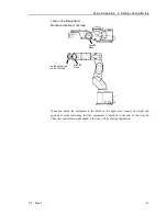
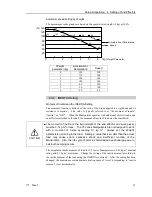
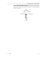
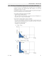
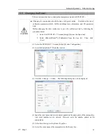
Calculate the Weight parameter by using the formula below and enter the value.
Weight Parameter Formula
Weight parameter =M
w
+ W
a
+ W
b
M
w
W
a
W
b
: Load on the fore end of Arm #6 (kg)
: Equivalent weight of the Arm #4 deck (kg)
: Equivalent weight of the Arm #5 deck (kg)
W
a
=M
a
(L
a
)
2
/(L)
2
W
b
=M
b
(L
b
)
2
/(L)
2
M
a
M
b
L
L
a
L
b
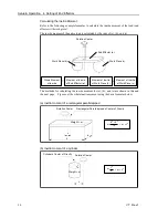
: Weight of the air valve on the Arm #4 deck
: Weight of the camera on the Arm #5 deck
: Length of the upper arm (480 mm)
: Distance between the Joint #3 and the center of gravity of
the air valve on the Arm #4 deck (mm)
: Distance between the Joint #3 and the center of gravity
of the camera on the Arm #5 deck (mm)
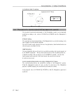
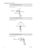
<Example> The fore end of the Arm #6 is 480mm (L) away from the Joint #3
of VT6-A901S* (VT6L).
Load on the fore-end of Arm #6 is 5 kg (M
w
).
Load on the Arm #4 deck is 1.5 kg (M
a
).
The deck is 150 mm (L
a
) away from Joint #3.
Load on the Arm #5 deck is 1.0 kg (M
b
).
The deck is 390 mm (L
b
) away from the Joint #3.
W
a
=1.5×150
2
/480
2
=0.15
→
0.2 (round up)
W
b
=1.0×390
2
/480
2
=0.66
→
0.7 (round up)
M
w
+W
a
+W
b
=5+0.2+0.7=5.9
Enter “5.9” for the Weight parameter.
Summary of Contents for VT Series
Page 1: ...6 Axis Robots VT series MANIPULATOR MANUAL Rev 1 EM18YR3817F ...
Page 2: ...MANIPULATOR MANUAL VT series Rev 1 ...
Page 8: ...vi VT Rev 1 ...
Page 16: ...TABLE OF CONTENTS xiv VT Rev 1 ...
Page 18: ......
Page 31: ...Setup Operation 2 Specifications VT Rev 1 15 2 4 Outer Dimensions ...
Page 32: ...Setup Operation 2 Specifications 16 VT Rev 1 Unit mm ...
Page 33: ...Setup Operation 2 Specifications VT Rev 1 17 2 5 Standard Motion Range Unit mm ...
Page 130: ......
Page 138: ...Maintenance 3 Manipulator Structure 122 VT Rev 1 3 Manipulator Structure ...

