Setup & Operation 4. Setting of End Effectors
VT Rev.1
43
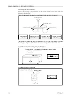
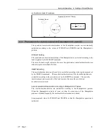
Example: Calculation of the critical dimension of the load (a) when the load is 6 kg.
Center of gravity by the allowable moment control:
12.0 Nm/(6 kg×9.8 m/s
2
) = 0.204 m = 204 mm
Center of gravity by the allowable inertia moment control:
(0.3 kgm2/6 kg)1/2 = 0.223 m = 223 mm
Due to the allowable moment control, center of gravity for the load limit is 212 mm from
the Arm #5 rotation center.
Distance (a) from the flange to the center of gravity for the load limit
= 204 mm
-
80 mm = 124 mm
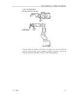
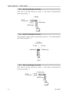
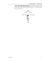
Critical Dimension of Load
Arm #J6
Rotation Center
Load’s Center of Gravity
Flange
Arm #J5
Rotation Center
[Unit: mm]
Summary of Contents for VT Series
Page 1: ...6 Axis Robots VT series MANIPULATOR MANUAL Rev 1 EM18YR3817F ...
Page 2: ...MANIPULATOR MANUAL VT series Rev 1 ...
Page 8: ...vi VT Rev 1 ...
Page 16: ...TABLE OF CONTENTS xiv VT Rev 1 ...
Page 18: ......
Page 31: ...Setup Operation 2 Specifications VT Rev 1 15 2 4 Outer Dimensions ...
Page 32: ...Setup Operation 2 Specifications 16 VT Rev 1 Unit mm ...
Page 33: ...Setup Operation 2 Specifications VT Rev 1 17 2 5 Standard Motion Range Unit mm ...
Page 130: ......
Page 138: ...Maintenance 3 Manipulator Structure 122 VT Rev 1 3 Manipulator Structure ...

