11 16-BIT TIMER (T16)
S1C17001 TECHNICAL MANUAL
EPSON
121
0x4226/0x4246/0x4266: 16-bit Timer Ch.
x
Control Registers (T16_CTL
x
)
Register name Address
Bit
Name
Function
Setting
Init. R/W
Remarks
16-bit Timer
Ch.
x
Control
Register
(T16_CTL
x
)
0x4226
0x4246
0x4266
(16 bits)
D15–11
–
reserved
–
–
–
0 when being read.
D10
CKACTV
External clock active level select
1 High
0 Low
1
R/W
D9–8
CKSL[1:0]
Input clock and pulse width
measurement mode select
CKSL[1:0]
Mode
0x0
R/W
0x3
0x2
0x1
0x0
reserved
Pulse width
External clock
Internal clock
D7–5
–
reserved
–
–
–
0 when being read.
D4
TRMD
Count mode select
1 One shot
0 Repeat
0
R/W
D3–2
–
reserved
–
–
–
0 when being read.
D1
PRESER
Timer reset
1 Reset
0 Ignored
0
W
D0
PRUN
Timer run/stop control
1 Run
0 Stop
0
R/W
Note: The “
x
” in the register names indicates the channel number (0 to 2).
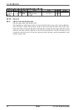
0x4226: 16-bit Timer Ch.0 Control Register (T16_CTL0)
0x4246: 16-bit Timer Ch.1 Control Register (T16_CTL1)
0x4266: 16-bit Timer Ch.2 Control Register (T16_CTL2)
D[15:11] Reserved
D10
CKACTV: External Clock Active Level Select Bit
Selects the external input pulse polarity or external clock counting edge.
1 (R/W): Active High/Rising edge (default)
0 (R/W): Active Low/Falling edge
This setting determines whether the external input clock rising edge or falling edge is used for counting
in external clock mode (when CKSL[1:0] = 0x1). In pulse width measurement mode (when CKSL[1:0]
= 0x2), this setting determines external input pulse polarity.
D[9:8]
CKSL[1:0]: Input Clock and Pulse Width Measurement Mode Select Bits
Select the 16-bit timer operating mode.
Table 11.9.3: Operating mode selection
CKSL[1:0]
Operating mode
0x3
Reserved
0x2
Pulse width measurement mode
0x1
External clock mode
0x0
Internal clock mode
(Default: 0x0)
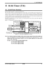
Internal clock mode uses the prescaler output clock as the count clock. The timer counts down from
the initial value set in the reload data register and outputs an underflow signal when the counter under-
flows. The underflow signal is used to generate an interrupt and an internal serial interface clock. The
time until underflow occurs can be finely programmed by selecting the prescaler clock and initial coun-
ter value, allowing its use for serial transfer clock generation and sporadic time measurement.
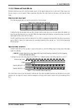
External clock mode uses the clock and pulses input via the input/output ports (Ch.0: P16, Ch.1: P07,
Ch.2: P06) as a count clock and can also be used as an event counter. Timer operations other than the
input clock are the same as for internal clock mode.
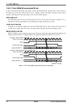
In pulse width measurement mode, when pulses with the specified polarity are input from the external
clock port, the internal clock is fed only while the signal is active, enabling counting. This enables inter-
rupt generation and input pulse width measurements for pulse inputs of the specified width or greater.
D[7:5] Reserved
Summary of Contents for S1C17001
Page 1: ...Technical Manual S1C17001 CMOS 16 BIT SINGLE CHIP MICROCONTROLLER ...
Page 33: ...4 POWER SUPPLY VOLTAGE 24 EPSON S1C17001 TECHNICAL MANUAL This page intentionally left blank ...
Page 63: ...6 INITERRUPT CONTROLLER 54 EPSON S1C17001 TECHNICAL MANUAL This page intentionally left blank ...
Page 87: ...8 CLOCK GENERATOR CLG 78 EPSON S1C17001 TECHNICAL MANUAL This page intentionally left blank ...
Page 91: ...9 PRESCALER PSC 82 EPSON S1C17001 TECHNICAL MANUAL This page intentionally left blank ...
Page 133: ...11 16 BIT TIMER T16 124 EPSON S1C17001 TECHNICAL MANUAL This page intentionally left blank ...
Page 211: ...16 STOPWATCH TIMER SWT 202 EPSON S1C17001 TECHNICAL MANUAL This page intentionally left blank ...
Page 219: ...17 WATCHDOG TIMER WDT 210 EPSON S1C17001 TECHNICAL MANUAL This page intentionally left blank ...
Page 241: ...18 UART 232 EPSON S1C17001 TECHNICAL MANUAL This page intentionally left blank ...
Page 277: ...20 I2 C 268 EPSON S1C17001 TECHNICAL MANUAL This page intentionally left blank ...
Page 313: ...25 PACKAGE 304 EPSON S1C17001 TECHNICAL MANUAL This page intentionally left blank ...

