14 8-BIT OSC1 TIMER (T8OSC1)
S1C17001 TECHNICAL MANUAL
EPSON
167
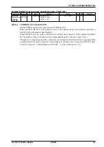
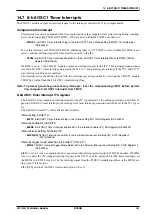
14.7 8-bit OSC1 Timer Interrupts
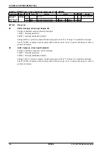
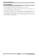
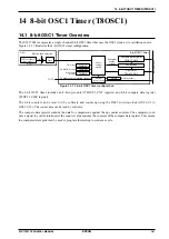
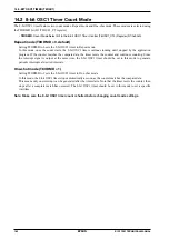
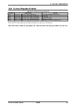
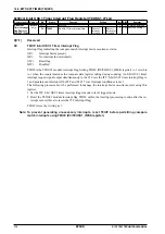
The T8OSC1 module outputs an interrupt request to the interrupt controller (ITC) by compare match.
Compare match interrupt
This interrupt request is generated when the counter matches the compare data register setting during counting.
It sets the interrupt flag T8OIF (D0/T8OSC1_IFLG register) within the T8OSC1 module to 1.
∗
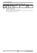
T8OIF
: 8-bit OSC1 Timer Interrupt Flag in the 8-bit OSC1 Timer Interrupt Flag (T8OSC1_IFLG) Register
(D0/0x50c4)
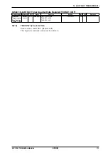
To use this interrupt, set T8OIE (D0/T8OSC1_IMSK register) to 1. If T8OIE is set to 0 (default), T8OIE is not
set to 1, and the interrupt request for this factor is not sent to the ITC.
∗
T8OIE
: 8-bit OSC1 Timer Interrupt Enable Bit in the 8-bit OSC1 Timer Interrupt Mask (T8OSC1_IMSK)
Register (D0/0x50c3)
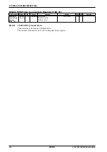
If T8OIF is set to 1, the T8OSC1 module outputs an interrupt request to the ITC. This interrupt request signal
sets the 8-bit OSC1 timer interrupt flag inside the ITC to 1 and generates an interrupt if the ITC and S1C17
core interrupt conditions are satisfied.
The interrupt factor should be cleared with the interrupt processing routine by resetting the T8OSC1 module
T8OIF (to 1) rather than the 8-bit OSC1 timer interrupt flag.
Note: To prevent generating unnecessary interrupts, reset the corresponding T8OIF before permit-
ting compare 8-bit OSC1 interrupts from T8OIE.
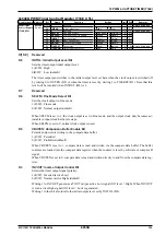
8-bit OSC1 timer interrupt ITC register
The 8-bit OSC timer outputs an interrupt signal to the ITC is generated by the settings previously described. To
generate 8-bit OSC timer interrupts, the interrupt level and interrupt permission should be set in the ITC regis-
ter.
The 8-bit OSC timer ITC control bits are shown below.
Interrupt flag inside ITC
∗
EIFT4
: 8-bit OSC1 Timer Interrupt Flag in the Interrupt Flag (ITC_IFLG) Register (D4/0x4300)
Interrupt enable bit inside ITC
∗
EIEN4
: 8-bit OSC1 Timer Interrupt Enable Bit in the Interrupt Enable (ITC_EN) Register (D4/0x4302)
Interrupt level setting bit inside ITC
∗
EILV4[2:0]
: T8OSC1 Interrupt Level Bits in the External Interrupt Level Setup (ITC_ELV2) Register 2
(D[2:0]/0x430a)
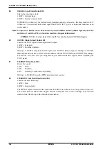
Interrupt trigger mode selection bit inside ITC (Fix at 1)
∗
EITG4
: T8OSC1 Interrupt Trigger Mode Select Bit in the External Interrupt Level Setup (ITC_ELV2) Register 2
(D4/0x430a)
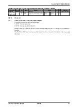
EIFT4 is set to 1 when a compare match is generated with interrupt permitted in the T8OSC1 module. If EIEN4
is set to 1 here, the ITC sends an interrupt request to the S1C17 core. To prevent 8-bit OSC timer interrupts, set
the EIEN4 to 0. EIFT4 is set to 1 by the interrupt signal from the T8OSC1 module regardless of the EIEN4 set-
ting (even if it is set to 0).
EILV4[2:0] sets the 8-bit OSC1 timer interrupt level (0 to 7).
Summary of Contents for S1C17001
Page 1: ...Technical Manual S1C17001 CMOS 16 BIT SINGLE CHIP MICROCONTROLLER ...
Page 33: ...4 POWER SUPPLY VOLTAGE 24 EPSON S1C17001 TECHNICAL MANUAL This page intentionally left blank ...
Page 63: ...6 INITERRUPT CONTROLLER 54 EPSON S1C17001 TECHNICAL MANUAL This page intentionally left blank ...
Page 87: ...8 CLOCK GENERATOR CLG 78 EPSON S1C17001 TECHNICAL MANUAL This page intentionally left blank ...
Page 91: ...9 PRESCALER PSC 82 EPSON S1C17001 TECHNICAL MANUAL This page intentionally left blank ...
Page 133: ...11 16 BIT TIMER T16 124 EPSON S1C17001 TECHNICAL MANUAL This page intentionally left blank ...
Page 211: ...16 STOPWATCH TIMER SWT 202 EPSON S1C17001 TECHNICAL MANUAL This page intentionally left blank ...
Page 219: ...17 WATCHDOG TIMER WDT 210 EPSON S1C17001 TECHNICAL MANUAL This page intentionally left blank ...
Page 241: ...18 UART 232 EPSON S1C17001 TECHNICAL MANUAL This page intentionally left blank ...
Page 277: ...20 I2 C 268 EPSON S1C17001 TECHNICAL MANUAL This page intentionally left blank ...
Page 313: ...25 PACKAGE 304 EPSON S1C17001 TECHNICAL MANUAL This page intentionally left blank ...

