13 PWM & CAPTURE TIMER (T16E)
150
EPSON
S1C17001 TECHNICAL MANUAL
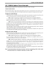
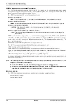
PWM & capture timer interrupt ITC register
The T16E module outputs an interrupt signal to the ITC if a compare match with interrupt permitted is gener-
ated by the settings previously described. To generate PWM & capture timer interrupts, the interrupt level and
interrupt permission should be set in the ITC register.
The PWM & capture timer ITC control bits are shown below.
Interrupt flag inside ITC
∗
EIFT7
: PWM & Capture Timer Interrupt Flag in the Interrupt Flag (ITC_IFLG) Register (D7/0x4300)
Interrupt enable bit inside ITC
∗
EIEN7
: PWM & Capture Timer Interrupt Enable Bit in the Interrupt Enable (ITC_EN) Register (D7/0x4302)
Interrupt level setting bit inside ITC
∗
EILV7[2:0]
: T16E Interrupt Level Bits in the External Interrupt Level Setup (ITC_ELV3) Register 3
(D[10:8]/0x430c)
Interrupt trigger mode selection bit inside ITC (Fix at 1)
∗
EITG7
: T16E Interrupt Trigger Mode Select Bit in the External Interrupt Level Setup (ITC_ELV3) Register 3
(D12/0x430c)
EIFT7 is set to 1 when a compare match is generated with interrupt permitted in the T16E module. If EIEN7 is
set to 1 here, the ITC sends an interrupt request to the S1C17 core. To prevent PWM & capture timer interrupts,
set the EIEN7 to 0. EIFT7 is set to 1 by the interrupt signal from the T16E module regardless of the EIEN7 set-
ting (even if it is set to 0).
EILV7[2:0] sets the PWM & capture timer interrupt level (0 to 7).
The S1C17 core accepts interrupts when the following conditions are satisfied:
• The interrupt enable bit has been set to 1.
• The PSR (S1C17 core internal processor status register) IE (interrupt enable) bit has been set to 1.
• The PWM & capture timer interrupt has been set to a higher interrupt level than that set for the PSR IL (interrupt
level).
• No other interrupt factors having higher precedence (e.g., NMI) are present.
For detailed information on these interrupt control registers and operations when interrupts occur, refer to “6
Interrupt Controller (ITC).”
Note: The following processes must be performed to manage the interrupt factor occurrence state
using the T16E module interrupt flag.
1. Set the ITC PWM & capture timer interrupt trigger mode to level trigger mode.
2. Reset the T16E module interrupt flags CAIF and CBIF within the interrupt processing rou-
tine after the interrupt occurs (this also resets the ITC interrupt flag).
Interrupt vectors
The PWM & capture timer interrupt vector numbers and vector addresses are listed below.
Vector number: 11 (0x0b)
Vector
address:
0x802c
Summary of Contents for S1C17001
Page 1: ...Technical Manual S1C17001 CMOS 16 BIT SINGLE CHIP MICROCONTROLLER ...
Page 33: ...4 POWER SUPPLY VOLTAGE 24 EPSON S1C17001 TECHNICAL MANUAL This page intentionally left blank ...
Page 63: ...6 INITERRUPT CONTROLLER 54 EPSON S1C17001 TECHNICAL MANUAL This page intentionally left blank ...
Page 87: ...8 CLOCK GENERATOR CLG 78 EPSON S1C17001 TECHNICAL MANUAL This page intentionally left blank ...
Page 91: ...9 PRESCALER PSC 82 EPSON S1C17001 TECHNICAL MANUAL This page intentionally left blank ...
Page 133: ...11 16 BIT TIMER T16 124 EPSON S1C17001 TECHNICAL MANUAL This page intentionally left blank ...
Page 211: ...16 STOPWATCH TIMER SWT 202 EPSON S1C17001 TECHNICAL MANUAL This page intentionally left blank ...
Page 219: ...17 WATCHDOG TIMER WDT 210 EPSON S1C17001 TECHNICAL MANUAL This page intentionally left blank ...
Page 241: ...18 UART 232 EPSON S1C17001 TECHNICAL MANUAL This page intentionally left blank ...
Page 277: ...20 I2 C 268 EPSON S1C17001 TECHNICAL MANUAL This page intentionally left blank ...
Page 313: ...25 PACKAGE 304 EPSON S1C17001 TECHNICAL MANUAL This page intentionally left blank ...

