15 CLOCK TIMER (TC)
S1C17001 TECHNICAL MANUAL
EPSON
187
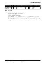
0x5003: Clock Timer Interrupt Flag Register (CT_IFLG)
Register name Address
Bit
Name
Function
Setting
Init. R/W
Remarks
Clock Timer
Interrupt Flag
Register
(CT_IFLG)
0x5003
(8 bits)
D7–4
–
reserved
–
–
–
0 when being read.
D3
CTIF32
32 Hz interrupt flag
1 Cause of
interrupt
occurred
0 Cause of
interrupt not
occurred
0
R/W Reset by writing 1.
D2
CTIF8
8 Hz interrupt flag
0
R/W
D1
CTIF2
2 Hz interrupt flag
0
R/W
D0
CTIF1
1 Hz interrupt flag
0
R/W
This register indicates the occurrence state of interrupt factors due to clock timer 32 Hz, 8 Hz, 2 Hz, and 1 Hz sig-
nals. If a clock timer interrupt occurs, identify the interrupt factor (frequency) by reading the interrupt flag in this
register. CTIF* are CT module interrupt flags corresponding to the individual 32 Hz, 8 Hz, 2 Hz, and 1 Hz inter-
rupts. It is set to 1 at the falling edge of each signal if CTIE* (CT_IMSK register) is set to 1. The clock timer inter-
rupt request signal is output to the ITC at the same time. This interrupt request signal sets the clock timer interrupt
flag in the ITC to 1 and generates an interrupt if the ITC and S1C17 core interrupt conditions are met.
The following processes must be performed to manage the interrupt factor occurrence state using this register.
1. Set the ITC clock timer interrupt trigger mode to level trigger mode.
2. Reset the CT module interrupt flag within the interrupt processing routine after the interrupt occurs (this also re-
sets the ITC interrupt flag).
CTIF* is reset by writing as 1.
Note: To prevent generating unnecessary interrupts, CTIF* must be reset before permitting clock
timer interrupts using CTIE.*
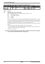
D3
CTIF32: 32 Hz Interrupt Flag
Interrupt flag indicating the 32 Hz interrupt factor occurrence status.
1(R):
Interrupt factor present
0(R):
No interrupt factor (default)
1(W):
Reset
flag
0(W):
Disabled
Setting CTIE32 (D3/CT_IMSK register) to 1 sets CTIF32 to 1 at the 32 Hz signal falling edge.
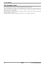
D2
CTIF8: 8 Hz Interrupt Flag
Interrupt flag indicating the 8 Hz interrupt factor occurrence status.
1(R):
Interrupt factor present
0(R):
No interrupt factor (default)
1(W):
Reset
flag
0(W):
Disabled
Setting CTIE8 (D2/CT_IMSK register) to 1 sets CTIF8 to 1 at the 8 Hz signal falling edge.
D1
CTIF2: 2 Hz Interrupt Flag
Interrupt flag indicating the 2 Hz interrupt factor occurrence status.
1(R):
Interrupt factor present
0(R):
No interrupt factor (default)
1(W):
Reset
flag
0(W):
Disabled
Setting CTIE2 (D1/CT_IMSK register) to 1 sets CTIF2 to 1 at the 2 Hz signal falling edge.
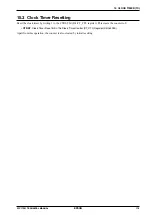
D0
CTIF1: 1 Hz Interrupt Flag
Interrupt flag indicating the 1 Hz interrupt factor occurrence status.
1(R):
Interrupt factor present
0(R):
No interrupt factor (default)
1(W):
Reset
flag
0(W):
Disabled
Setting CTIE1 (D0/CT_IMSK register) to 1 sets CTIF1 to 1 at the 1 Hz signal falling edge.
Summary of Contents for S1C17001
Page 1: ...Technical Manual S1C17001 CMOS 16 BIT SINGLE CHIP MICROCONTROLLER ...
Page 33: ...4 POWER SUPPLY VOLTAGE 24 EPSON S1C17001 TECHNICAL MANUAL This page intentionally left blank ...
Page 63: ...6 INITERRUPT CONTROLLER 54 EPSON S1C17001 TECHNICAL MANUAL This page intentionally left blank ...
Page 87: ...8 CLOCK GENERATOR CLG 78 EPSON S1C17001 TECHNICAL MANUAL This page intentionally left blank ...
Page 91: ...9 PRESCALER PSC 82 EPSON S1C17001 TECHNICAL MANUAL This page intentionally left blank ...
Page 133: ...11 16 BIT TIMER T16 124 EPSON S1C17001 TECHNICAL MANUAL This page intentionally left blank ...
Page 211: ...16 STOPWATCH TIMER SWT 202 EPSON S1C17001 TECHNICAL MANUAL This page intentionally left blank ...
Page 219: ...17 WATCHDOG TIMER WDT 210 EPSON S1C17001 TECHNICAL MANUAL This page intentionally left blank ...
Page 241: ...18 UART 232 EPSON S1C17001 TECHNICAL MANUAL This page intentionally left blank ...
Page 277: ...20 I2 C 268 EPSON S1C17001 TECHNICAL MANUAL This page intentionally left blank ...
Page 313: ...25 PACKAGE 304 EPSON S1C17001 TECHNICAL MANUAL This page intentionally left blank ...

