19 SPI
S1C17001 TECHNICAL MANUAL
EPSON
247
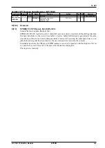
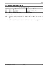
D1
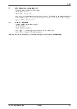
MSSL: Master/Slave Mode Select Bit
Sets the SPI module to Master or Slave mode.
1 (R/W): Master mode
0 (R/W): Slave mode (default)
Setting MSSL to 1 selects Master mode; setting it to 0 selects Slave mode. Master mode performs data
transfer with the clock generated by the 16-bit timer Ch.1. In Slave mode, data is transferred by input-
ting the clock from the master device.
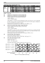
D0
SPEN: SPI Enable Bit
Permits or prohibits SPI module operation.
1 (R/W): Permitted
0 (R/W): Prohibited (default)
Setting SPEN to 1 starts the SPI module operation, enabling data transfer.
Setting SPEN to 0 stops the SPI module operation.
Note: The SPEN bit should be set to 0 before setting the CPHA, CPOL, and MSSL bits.
Summary of Contents for S1C17001
Page 1: ...Technical Manual S1C17001 CMOS 16 BIT SINGLE CHIP MICROCONTROLLER ...
Page 33: ...4 POWER SUPPLY VOLTAGE 24 EPSON S1C17001 TECHNICAL MANUAL This page intentionally left blank ...
Page 63: ...6 INITERRUPT CONTROLLER 54 EPSON S1C17001 TECHNICAL MANUAL This page intentionally left blank ...
Page 87: ...8 CLOCK GENERATOR CLG 78 EPSON S1C17001 TECHNICAL MANUAL This page intentionally left blank ...
Page 91: ...9 PRESCALER PSC 82 EPSON S1C17001 TECHNICAL MANUAL This page intentionally left blank ...
Page 133: ...11 16 BIT TIMER T16 124 EPSON S1C17001 TECHNICAL MANUAL This page intentionally left blank ...
Page 211: ...16 STOPWATCH TIMER SWT 202 EPSON S1C17001 TECHNICAL MANUAL This page intentionally left blank ...
Page 219: ...17 WATCHDOG TIMER WDT 210 EPSON S1C17001 TECHNICAL MANUAL This page intentionally left blank ...
Page 241: ...18 UART 232 EPSON S1C17001 TECHNICAL MANUAL This page intentionally left blank ...
Page 277: ...20 I2 C 268 EPSON S1C17001 TECHNICAL MANUAL This page intentionally left blank ...
Page 313: ...25 PACKAGE 304 EPSON S1C17001 TECHNICAL MANUAL This page intentionally left blank ...


