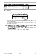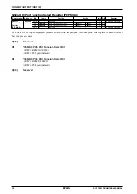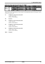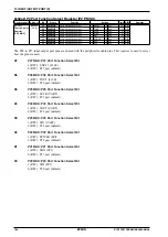
11 16-BIT TIMER (T16)
114
EPSON
S1C17001 TECHNICAL MANUAL
11.6 16-bit Timer RUN/STOP Control
Make the following settings before starting the 16-bit timer.
(1) Select the operating mode (Internal clock, External clock, or Pulse width measurement). See Section 11.2.
(2) For Internal clock or Pulse width measurement mode, select the count clock (prescaler output clock). See Sec-
tion 11.2.1.
(3) Set the count mode (One-shot or Repeat). See Section 11.3.
(4) Calculate the initial counter value and set the reload data register. See Section 11.4.
(5) Reset the timer and preset the counter to the initial value. See Section 11.5.
(6) If using timer interrupts, set the interrupt level and allow interrupts for the relevant timer channel. See Section
11.8.
To start the 16-bit timer, write 1 to PRUN (D0/T16_CTL
x
register).
∗
PRUN
: Timer Run/Stop Control Bit in the 16-bit Timer Ch.
x
Control (T16_CTL
x
) Register (D0/0x4226/0x4246/
0x4266)
The timer starts counting down from the initial value or from the current counter value if no initial value was pre-
set. When the counter underflows, the timer outputs an underflow pulse and presets the counter to the initial value.
An interrupt request is sent simultaneously to the interrupt controller (ITC).
If One-shot mode is set, the timer stops the count.
If Repeat mode is set, the timer continues to count from the reloaded initial value.
Write 0 to PRUN to stop the 16-bit timer via the application program. The counter stops counting and retains the
current counter value until either the timer is reset or restarted. To restart the count from the initial value, the timer
should be reset before writing 1 to PRUN.
Count clock
PRESER writing
PRUN
Counter
Interrupt request
0
1
n-1
n
n
Count clock
PRESER writing
PRUN
Counter
Interrupt request
0
1
n-1
n
n
0
1
n-1
n
n-1
One-shot mode
Repeat mode
Reset by hardware
Set by software
Set by software
Reset by software
Figure 11.6.1: Count operation
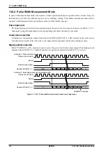
In Pulse width measurement mode, the timer counts only while PRUN is set to 1 and the external input signal is at
the specified active level. When the external input signal becomes inactive, the 16-bit timer stops counting and re-
tains the counter value until the next active level input. (See Figure 11.2.3.1.)
Summary of Contents for S1C17001
Page 1: ...Technical Manual S1C17001 CMOS 16 BIT SINGLE CHIP MICROCONTROLLER ...
Page 33: ...4 POWER SUPPLY VOLTAGE 24 EPSON S1C17001 TECHNICAL MANUAL This page intentionally left blank ...
Page 63: ...6 INITERRUPT CONTROLLER 54 EPSON S1C17001 TECHNICAL MANUAL This page intentionally left blank ...
Page 87: ...8 CLOCK GENERATOR CLG 78 EPSON S1C17001 TECHNICAL MANUAL This page intentionally left blank ...
Page 91: ...9 PRESCALER PSC 82 EPSON S1C17001 TECHNICAL MANUAL This page intentionally left blank ...
Page 133: ...11 16 BIT TIMER T16 124 EPSON S1C17001 TECHNICAL MANUAL This page intentionally left blank ...
Page 211: ...16 STOPWATCH TIMER SWT 202 EPSON S1C17001 TECHNICAL MANUAL This page intentionally left blank ...
Page 219: ...17 WATCHDOG TIMER WDT 210 EPSON S1C17001 TECHNICAL MANUAL This page intentionally left blank ...
Page 241: ...18 UART 232 EPSON S1C17001 TECHNICAL MANUAL This page intentionally left blank ...
Page 277: ...20 I2 C 268 EPSON S1C17001 TECHNICAL MANUAL This page intentionally left blank ...
Page 313: ...25 PACKAGE 304 EPSON S1C17001 TECHNICAL MANUAL This page intentionally left blank ...


