6 INITERRUPT CONTROLLER
36
EPSON
S1C17001 TECHNICAL MANUAL
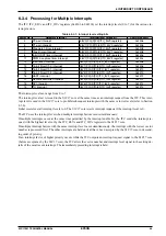
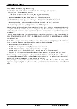
6.3.6 S1C17 Core Interrupt Processing
Maskable interrupts for the S1C17 core occur when all of the following conditions are met:
• ITEN (D0/ITC_CTL register) has been set to 1.
∗
ITEN
: ITC Enable Bit in the ITC Control (ITC_CTL) Register (D0/0x4304)
• The corresponding interrupt enable bit has been set to 1 for the interrupt factor.
• The PSR (S1C17 core internal processor status register) IE (interrupt enable) bit has been set to 1.
• The interrupt factor has a higher interrupt level set than that set for the PSR IL (interrupt level).
• No other interrupt factors having higher procedence (e.g., NMI) are present.
When an interrupt factor occurs, the corresponding interrupt flag is set to 1. This state is maintained until reset by
the program or hardware (for interrupts set in level trigger mode). The interrupt factor is not cleared even if the
conditions listed above remain unmet when the interrupt factor occurs. An interrupt occurs when the above condi-
tions are met.
If multiple maskable interrupt factors occur simultaneously, the interrupt factor with the highest level becomes the
subject of the interrupt request to the S1C17 core. Interrupts with lower levels are held until the above conditions
are subsequently met.
The S1C17 core samples interrupt requests for each cycle. On accepting an interrupt request, the S1C17 core
switches to interrupt processing when execution of the current command is complete.
Interrupt processing involves the following steps:
(1) The PSR and current program counter (PC) value is moved to the stack.
(2) The PSR IE bit is reset to 0 (preventing subsequent maskable interrupts).
(3) The PSR IL is set to the received interrupt level. (The NMI does not affect interrupt levels.)
(4) The vector for the interrupt factor occurring is loaded to the PC to execute the interrupt processing routine.
When an interrupt is received, (2) prevents subsequent maskable interrupts. Setting the IE bit to 1 within the inter-
rupt processing routine allows handling of multiple interrupts. In this case, IL is changed by (3), and only interrupts
with higher levels than those already being processed will be accepted.
Ending interrupt processing routines using a reti command returns the PSR to the state before the interrupt. The
program resumes processing following the command being executed at the time the interrupt occurred via the next
branch.
Summary of Contents for S1C17001
Page 1: ...Technical Manual S1C17001 CMOS 16 BIT SINGLE CHIP MICROCONTROLLER ...
Page 33: ...4 POWER SUPPLY VOLTAGE 24 EPSON S1C17001 TECHNICAL MANUAL This page intentionally left blank ...
Page 63: ...6 INITERRUPT CONTROLLER 54 EPSON S1C17001 TECHNICAL MANUAL This page intentionally left blank ...
Page 87: ...8 CLOCK GENERATOR CLG 78 EPSON S1C17001 TECHNICAL MANUAL This page intentionally left blank ...
Page 91: ...9 PRESCALER PSC 82 EPSON S1C17001 TECHNICAL MANUAL This page intentionally left blank ...
Page 133: ...11 16 BIT TIMER T16 124 EPSON S1C17001 TECHNICAL MANUAL This page intentionally left blank ...
Page 211: ...16 STOPWATCH TIMER SWT 202 EPSON S1C17001 TECHNICAL MANUAL This page intentionally left blank ...
Page 219: ...17 WATCHDOG TIMER WDT 210 EPSON S1C17001 TECHNICAL MANUAL This page intentionally left blank ...
Page 241: ...18 UART 232 EPSON S1C17001 TECHNICAL MANUAL This page intentionally left blank ...
Page 277: ...20 I2 C 268 EPSON S1C17001 TECHNICAL MANUAL This page intentionally left blank ...
Page 313: ...25 PACKAGE 304 EPSON S1C17001 TECHNICAL MANUAL This page intentionally left blank ...

