


Menu 6
Commander SK Advanced User Guide
87
Issue Number: 9 www.controltechniques.com
0
: Coast stop
1
: Ramp stop
2
: Ramp stop + dc injection
3
: DC Injection braking stop with detection of zero speed
4
: Timed dc injection braking stop
Stopping is in two distinct phases: decelerating to stop, and stopped. ( Table shows default values)
Once modes 3 or 4 have begun the drive must go through the ready state before being restarted either by stopping, tripping or being disabled.
Once DC injection braking has started, the drive cannot be restarted unless the drive is tripped or disabled.
The drive will enter one of the above stopping modes when the enable, run forward, run reverse, run or not stop terminals are opened, depending on
the programmed terminal configuration.
When the enable terminal is opened, the drive will always enter the coast to stop mode.
There is a delay of 65ms in the drives software when switching from run forward to run reverse or vice-versa. This delay is to allow the direction of
motor rotation to be changed without the drive entering one of the above selected stopping mode.
During each of the stopping mode sequences, there are two distinct phases:
•
decelerating to stop
•
stopped
Mode 1: Coast to stop
Pr
6.01
= 0
Phase 1
The output bridge of the drive is disabled.
Phase 2
The drive cannot be re-enabled for 2 seconds.
The 2 seconds delay in phase 2 allows the rotor flux to decay before the drive is allowed to be re-enabled. This 2 second time cannot be adjusted.
Mode 2: Ramp to stop
Pr
6.01
= 1 (default)
Phase 1
The drive will ramp down to zero frequency under the control of the selected ramp mode (Pr
2.04
) in the time set by the deceleration rate.
Phase 2
The drive will wait for 1 second with the output bridge enabled and then it will disable.
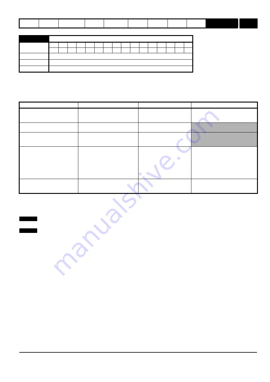
6.01
Stop mode select {31}
Coding
Bit
SP
FI
DE Txt VM DP ND RA NC NV
PT
US RW BU PS
1
1
1
Range
0 to 4
Default
1
Update rate
2 ms
Stopping Mode
Phase 1
Phase 2
Comments
0: Coast
Inverter disabled
Drive cannot be re-enabled for
a specific time period which is
drive size dependant.
Delay in phase 2 allows rotor flux to
decay.
1: Ramp
Ramp down to zero frequency
Wait for 1s with inverter
enabled
2: Ramp followed by DC injection
Ramp down to zero frequency
Inject DC at level specified by
Pr
6.06
for time defined by
Pr
6.07
3: DC injection with zero speed
detection
Low frequency current injection with
detection of low speed before next
phase
Inject DC at level specified by
Pr
6.06
for time defined by
Pr
6.07
The drive automatically senses low
speed and therefore it adjusts the
injection time to suit the application. If
the injection current level is too small
the drive will not sense low speed
(normally a minimum of 50-60% is
required).
4: Timed DC injection braking stop
Inject DC at level specified by
Pr
6.06
for time specified by Pr
6.07
Inject DC at level specified by
Pr
6.06
for 1s
The minimum total injection time is 1s
for phase 1 and 1s for phase 2, i.e. 2s
in total.
NOTE
NOTE
Summary of Contents for 2202
Page 199: ......
Page 200: ...0472 0001 09 ...


