36/112
WL31/WL31TG
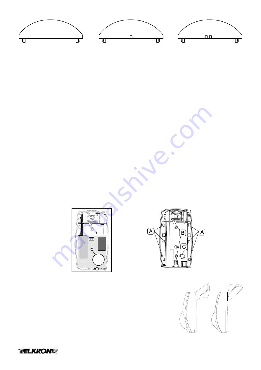
WIDE ANGLE protection
CURTAIN protection
LONG RANGE protection
4. Cut the cylindrical peg situated on the side of the lens and reinsert it so that the part of the lens which
corresponds to the field to be activated is down (dark area in the figure).
4.4.1.2 INSTALLATION WARNINGS
To install the detector correctly, please take the following precautions:
Do not install the detector on metallic surfaces or near big metallic objects.
Do not install the detectors near electromagnetic sources such as electric engines, reactors, electric panels, etc.
Do not install the detector where dust could accumulate.
Do not install the detector near heat sources or where it could be exposed to direct sun light.
Install the detector on a rigid surface without vibration, at a height of between 2 and 2.2 meters.
Refer to the detection diagrams to position the detector since this must detect all the movements in the protected area.
Avoid blind areas in the protected zone - these could be caused by furniture, shelves, plants, etc - within which
the intruder could move.
It is possible to install more detectors in the same room, without interference problems. If the detector must be
installed higher than 2.2 meters it is advisable to use the optional articulation and to tilt the detector down in order
to adapt the covered field to the real needs.
4.4.1.3 INSTALLATION WITHOUT BRACKET
To install the detector without the support of the articulation do as follows:
1. Write down a table to summarize the programming for the detector monitoring zone (if you followed our advice,
the address of the detector is written on an adhesive label attached on the back of the device).
2. If the detector is not open yet remove the cover.
3. Remove the supplied battery.
4.
Remove the electronic card by unscrewing the “V” screw and taking care not to touch the pyroelectric detector.
5. To authorize the removal protection device, break the plastic situated on the tamper key (C = tamper pre-set for
removal protection) and insert the supplied spring on the rear micro contact. Eliminate the JP2 bridge.
6. Fix the detector on the wall with the supplied plugs using the preset locations A (for corner fixing) or B (holes for
fixing on a flat surface).
7. Reposition the electronic card and fix it with its screw.
8. Reinsert the supplied battery and close the detector with its cover.
4.4.1.4 INSTALLATION WITH BRACKET
An articulation to install the detector is optionally available.
This articulation enables you to locate a removal protection tamper whose two
wires must be connected with the detector TAMPER terminals and whose JP1
bridge must be removed.
For the installation and the use of the articulation please refer to the product
specific instructions.
V


