xiii
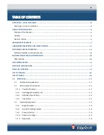
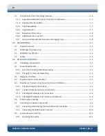
4.1.1 Topside Processor ............................................................................................................... 4-19
4.1.2 2000 Digital Telemetry Link ................................................................................................ 4-20
Selecting Negative Edge Triggering for the Optional Responder ............................... 4-21
5.1.1 Inspecting and Cleaning the Tow Vehicle and Tow Cable after Use .................................... 5-1
5.1.2 Inspecting and Cleaning the Underwater Connectors .......................................................... 5-1
5.1.3 Storage .................................................................................................................................. 5-2
5.1.4 Recommended Spares .......................................................................................................... 5-2
5.3.1 Disassembling the Tow Vehicle ............................................................................................ 5-3
5.3.2 Reassembling the Tow Vehicle ............................................................................................. 5-4
6.3.1 Equipment Required ............................................................................................................. 6-5
6.3.2 Transmission Verification ..................................................................................................... 6-5
6.3.3 Sonar Processor and Data Link ............................................................................................. 6-5
6.3.4 Topside Power Unit .............................................................................................................. 6-6
6.3.5 Command and Data Link ....................................................................................................... 6-6
6.3.6 Data Link ............................................................................................................................... 6-6
Summary of Contents for 2000-DSS
Page 20: ......
Page 56: ...Figure 4 2 2000 Digital Telemetry Link Electronics Block Diagram...
Page 57: ...Figure 4 3 2000 Digital Telemetry Link Wiring Diagram...
Page 59: ...Figure 4 4 Tow Vehicle Electronic Block Diagram...
Page 60: ...Figure 4 5 Tow Vehicle Interconnect Drawing...
Page 63: ...Figure 4 6 Armored Cable PMI Grip Unterminated Topside...
Page 64: ...Figure 4 7 Test Cable...
Page 77: ...5 13 Figure 5 16 Magnetic Declination Estimated Value Screen...
Page 79: ...5 15 getDeclination CR Figure 5 18...
Page 80: ......
Page 94: ......
Page 96: ......
Page 98: ......


