6.0: TROUBLESHOOTING
6-10
2000-DSS COMBINED SONAR
0009335_REV_D
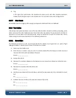
2.
Trig.
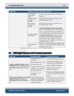
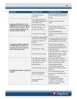
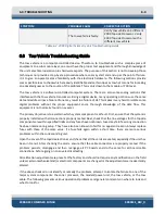
A TTL signal that synchronizes the topside and sub-sea units with other topside equipment.
Follows the SYNC signal input on the topside unit. It is not used in all system configurations.
6.3.7.7
Other Checks
Periodically check the integrity of the sea ground capacitor attached to the rear bulkhead.
6.3.8
Tow Cables
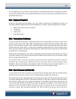
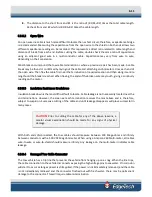
Historically, most system problems occur in the tow cable and their connectors. Before proceeding, verify
cable continuity from the shipboard end of the cable to the tow vehicle. The presence of a shorted or
open wire in a tow cable can be determined by using a multi-meter. An open or shorted wire can be
located using the techniques described in the following subsections.
6.3.8.1
Shorted Wire
The following procedure may be used to approximate the distance to a single short or a point of high
leakage between a conductor pair or from a conductor to a shield.
1.
Disconnect both cable ends.
2.
Short the two connector pins (or wires if un-terminated) of the shorted pair at both ends and
measure the total resistance between the ends.
R1+R2 =_______________
3.
Remove the shorts.
4.
Measure the resistance between a shorted pair on one end with an ohmmeter on the Rx1 scale.
R1+Rs =_______________
5.
Measure the resistance from the other end.
R2+Rs =_______________
6.
Add the measurements of 4) and 5) above, subtract the measurement of 2), and divide the result
by 2.
Rs =_________________
7.
Subtract the value of 6) from the measured values of 4) and 5).
R1 =_________________
R2 =_________________
Summary of Contents for 2000-DSS
Page 20: ......
Page 56: ...Figure 4 2 2000 Digital Telemetry Link Electronics Block Diagram...
Page 57: ...Figure 4 3 2000 Digital Telemetry Link Wiring Diagram...
Page 59: ...Figure 4 4 Tow Vehicle Electronic Block Diagram...
Page 60: ...Figure 4 5 Tow Vehicle Interconnect Drawing...
Page 63: ...Figure 4 6 Armored Cable PMI Grip Unterminated Topside...
Page 64: ...Figure 4 7 Test Cable...
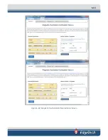
Page 77: ...5 13 Figure 5 16 Magnetic Declination Estimated Value Screen...
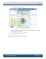
Page 79: ...5 15 getDeclination CR Figure 5 18...
Page 80: ......
Page 94: ......
Page 96: ......
Page 98: ......

