6-3
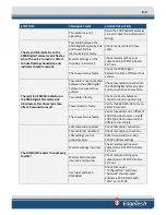
SYMPTOM
PROBABLE CAUSE
CORRECTIVE ACTION
The indicator is not
operating.
Open the 2000 Digital Telemetry
Link and check the indicator and
wiring.
The green LINK indicator on the
2000 Digital Telemetry Link flashes
when the unit is turned on. After 1
minute flashing should stop and
indicator should remain lit.
Tow cable between the
2000 Digital Telemetry Link
and tow vehicle is
disconnected or faulty.
Check connections and tow
cable.
Modem settings on the
topside are incorrect.
Check modem settings per
The tow vehicle is faulty.
Check the 2000 Digital
Telemetry Link on different tow
vehicle.
The red FISH POWER indicator on
the 2000 Digital Telemetry Link
illuminates after 10 seconds then
after 20 seconds turns off.
Tow cable is not connected
between the 2000 Digital
Telemetry Link and tow
vehicle.
Check tow cable connections to
the 2000 Digital Telemetry Link
and connection to tow vehicle.
Tow cable is faulty.
Check continuity between
connectors and proper wiring.
Power board is faulty.
Verify that RED LED D2 turns on
after 10 seconds.
The tow vehicle is faulty.
Verify tow vehicle on a different
2000 Topside Processor. Verify
2000 Topside Processor with a
different tow vehicle.
The DISCOVER reports “Cannot ping
towfish”
LAN cable disconnected.
Check LAN cable connection.
Tow cable disconnected.
Check tow cable connections.
LAN settings are not
properly setup.
for
TCP/IP address settings.
Modem settings incorrect.
Check modem settings per
Modem disconnected
internally on topside.
Check modem settings per
Improper settings in
DISCOVER.
Check that under
“Configuration” pull down
“Network” the displayed
address is 192.9.0.101 with
“Port” set to 1700.
Summary of Contents for 2000-DSS
Page 20: ......
Page 56: ...Figure 4 2 2000 Digital Telemetry Link Electronics Block Diagram...
Page 57: ...Figure 4 3 2000 Digital Telemetry Link Wiring Diagram...
Page 59: ...Figure 4 4 Tow Vehicle Electronic Block Diagram...
Page 60: ...Figure 4 5 Tow Vehicle Interconnect Drawing...
Page 63: ...Figure 4 6 Armored Cable PMI Grip Unterminated Topside...
Page 64: ...Figure 4 7 Test Cable...
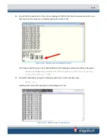
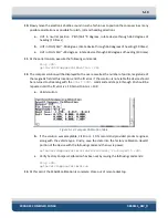
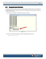
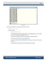
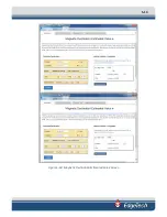
Page 77: ...5 13 Figure 5 16 Magnetic Declination Estimated Value Screen...
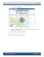
Page 79: ...5 15 getDeclination CR Figure 5 18...
Page 80: ......
Page 94: ......
Page 96: ......
Page 98: ......

