3-7
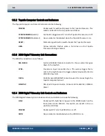
LAN:
Green indicator. Flashes continuously when an Ethernet
connection is established.
LINK:
Green indicator. Flashes while the 2000-DL is establishing a
reliable communications link with the side scan sonar.
Illuminates continuously when a reliable communications link
with the sonar is established.
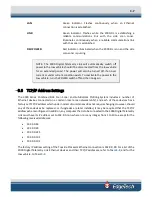
FISH POWER:
Red indicator. Illuminated when the 2000-DL is on and the side
scan sonar is pulsing.
NOTE:
The 2000 Digital Telemetry Link will automatically switch off
power to the tow vehicle should it be disconnected from the tow vehicle
for an extended period. The power will also be turned off if an over
current or under current condition exists. To reactivate the power to the
tow vehicle, turn the POWER switch off and then on again.
3.6
TCP/IP Address Settings
The 2000 Series Combined Side Scan Sonar and Sub-Bottom Profiling System includes a number of
Ethernet devices connected on a common local area network (LAN), and each of these devices has a
factory set TCP/IP address which under normal circumstances does not require changing. However, should
any of these devices be replaced, or if upgrades are later installed, it may be required that the TCP/IP
addresses be reconfigured. In addition, any computer that is to be connected to the 2000 Digital Telemetry
Link must have its IP address set to 192.9.0.nnn, where nnn is any integer from 1 to 100—except for the
following reserved addresses:
•
192.9.0.22
•
192.9.0.23
•
192.9.0.225
•
192.9.0.101
•
192.9.0.102
The factory IP address setting of the Topside Processor Ethernet connection is 192.9.0.99. For a list of the
2000 Digital Telemetry Link Ethernet devices and their TCP/IP addresses, refer to
, and for the
tow vehicle, to
Summary of Contents for 2000-DSS
Page 20: ......
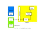
Page 56: ...Figure 4 2 2000 Digital Telemetry Link Electronics Block Diagram...
Page 57: ...Figure 4 3 2000 Digital Telemetry Link Wiring Diagram...
Page 59: ...Figure 4 4 Tow Vehicle Electronic Block Diagram...
Page 60: ...Figure 4 5 Tow Vehicle Interconnect Drawing...
Page 63: ...Figure 4 6 Armored Cable PMI Grip Unterminated Topside...
Page 64: ...Figure 4 7 Test Cable...
Page 77: ...5 13 Figure 5 16 Magnetic Declination Estimated Value Screen...
Page 79: ...5 15 getDeclination CR Figure 5 18...
Page 80: ......
Page 94: ......
Page 96: ......
Page 98: ......

