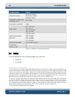
3-14
2000-DSS Combined Sonar
0009335_REV_D
6.
Verify that the heading, pitch and roll sensors are working correctly by rotating, tilting and rolling
the tow vehicle and observing the Heading, Pitch and Roll displays in the Lower Indicator bar in
the Main window.
7.
If a pressure sensor is installed, verify that the Pressure display indication is at or nearly zero. The
Pressure sensor can be zeroed on deck under External Device Controls.
8.
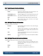
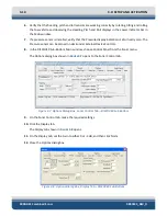
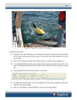
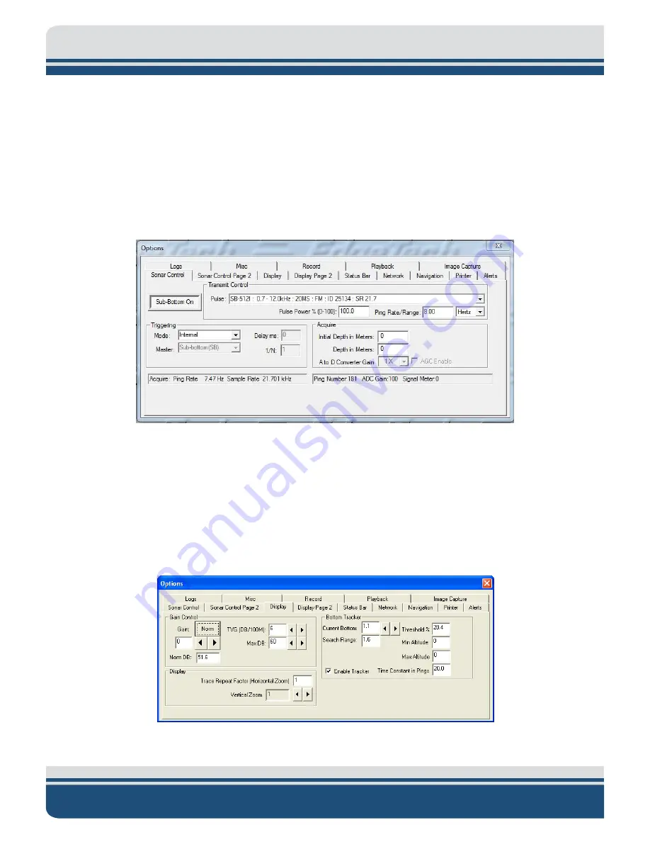
In the DISCOVER Sub-Bottom Main window, choose Control Panel from the Sonar menu.
The Options dialog box shown in
opens to the Sonar Control tab.
Figure 3-7: Options Dialog Box, Sonar Control Tab—DISCOVER Sub Bottom
9.
On the Sonar Control tab, make the required settings.
10.
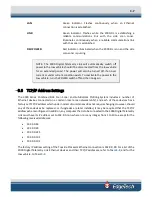
Click the Display tab.
The Display tab shown in
11.
On the Display tab, set the Gain to either 0 or -3 dB, and then click Norm.
12.
Close the Options dialog box.
Figure 3-8: Options Dialog Box, Display Tab—DISCOVER Sub-Bottom
Summary of Contents for 2000-DSS
Page 20: ......
Page 56: ...Figure 4 2 2000 Digital Telemetry Link Electronics Block Diagram...
Page 57: ...Figure 4 3 2000 Digital Telemetry Link Wiring Diagram...
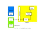
Page 59: ...Figure 4 4 Tow Vehicle Electronic Block Diagram...
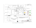
Page 60: ...Figure 4 5 Tow Vehicle Interconnect Drawing...
Page 63: ...Figure 4 6 Armored Cable PMI Grip Unterminated Topside...
Page 64: ...Figure 4 7 Test Cable...
Page 77: ...5 13 Figure 5 16 Magnetic Declination Estimated Value Screen...
Page 79: ...5 15 getDeclination CR Figure 5 18...
Page 80: ......
Page 94: ......
Page 96: ......
Page 98: ......

