3-8
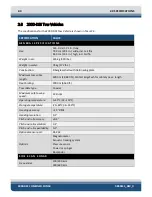
2000-DSS Combined Sonar
0009335_REV_D
DEVICE
TCP/IP ADDRESS
Net Burner board
192.9.0.102
ASDL Modem board
192.9.0.22
Wireless bridge
192.9.0.225
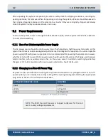
Table 3-2: Topside Computer TCP/IP Addresses
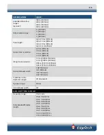
DEVICE
TCP/IP ADDRESS
CPU Board
192.9.0.101
ASDL Modem board
192.9.9.23
Table 3-3: 2000 Digital Telemetry Link Devices TCP/IP Addresses
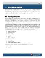
3.7
Connecting the System Components
Most of the system components, including some optional components, such as a printer and a navigation
system, connect to the Topside Processor. The tow vehicle and any optional external sonar systems
connect to the 2000 Digital Telemetry Link.
WARNING!
Do not connect the tow cable to the 2000 Digital Telemetry
Link before connecting it to the tow vehicle, otherwise injury or death
can occur if the exposed connector on the tow cable is energized. Always
connect the tow cable to the tow vehicle first.
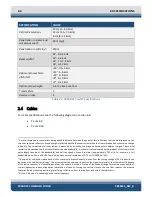
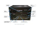
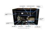
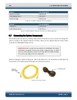
When connecting the system components, refer to sub-section
for the location and description of
the connectors. The cables used with the system are shown in
Figure 3-3: System Cables
Summary of Contents for 2000-DSS
Page 20: ......
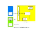
Page 56: ...Figure 4 2 2000 Digital Telemetry Link Electronics Block Diagram...
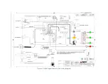
Page 57: ...Figure 4 3 2000 Digital Telemetry Link Wiring Diagram...
Page 59: ...Figure 4 4 Tow Vehicle Electronic Block Diagram...
Page 60: ...Figure 4 5 Tow Vehicle Interconnect Drawing...
Page 63: ...Figure 4 6 Armored Cable PMI Grip Unterminated Topside...
Page 64: ...Figure 4 7 Test Cable...
Page 77: ...5 13 Figure 5 16 Magnetic Declination Estimated Value Screen...
Page 79: ...5 15 getDeclination CR Figure 5 18...
Page 80: ......
Page 94: ......
Page 96: ......
Page 98: ......

