4-21
4.1.2.1
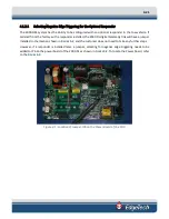
Selecting Negative Edge Triggering for the Optional Responder
The 2000-DSS system has the ability to be configured with an optional responder in the tow vehicle. If
ordered from the factory with a responder installed, the 2000-DL digital telemetry link will have a jumper
installed in the location shown in
, and the customer does not need to take any further steps.
However, if a responder is installed later, a jumper, selecting for negative edge triggering needs to be
added to JP6 on the power board of the 2000-DL as shown in
. To locate the Power board, refer
to the
F
IGURE
4-3
.
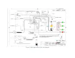
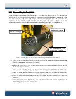
Figure 4-1: Location of Jumper JP6 on the Power Board of the FSIU
Summary of Contents for 2000-DSS
Page 20: ......
Page 56: ...Figure 4 2 2000 Digital Telemetry Link Electronics Block Diagram...
Page 57: ...Figure 4 3 2000 Digital Telemetry Link Wiring Diagram...
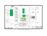
Page 59: ...Figure 4 4 Tow Vehicle Electronic Block Diagram...
Page 60: ...Figure 4 5 Tow Vehicle Interconnect Drawing...
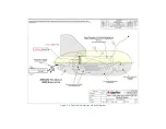
Page 63: ...Figure 4 6 Armored Cable PMI Grip Unterminated Topside...
Page 64: ...Figure 4 7 Test Cable...
Page 77: ...5 13 Figure 5 16 Magnetic Declination Estimated Value Screen...
Page 79: ...5 15 getDeclination CR Figure 5 18...
Page 80: ......
Page 94: ......
Page 96: ......
Page 98: ......

